Form O-Y P/N 273647R5, Page 33
Control Staged Gas
(2-stage, Option AG71
or 4-stage, Option
AG72 - applies to
Model YDSA only)
Sequence of Operation
:LVHQHUJL]HGDQGWKH'6FRQWUROPRGXOHYHUL¿HVWKDWWKHSUHVVXUH
switches are open.
2) Inducer (venter) is energized for pre-purge and the DS1 control module
YHUL¿HVWKDWWKHORZSUHVVXUHVZLWFKLVFORVHG
3) After the pre-purge period has elapsed (20 seconds), the DS1 control
module energizes the trial for ignition period (17 seconds).
4)$IWHUEORZHURQGHOD\VHFRQGVIURPÀDPHGHWHFWHGWKH
controller will energize the blower (supply fan).
5) If W2 is energized, the high gas output will energize.
6) After W1 and W2 are de-energized, the controller will run the blower-off
delay (120 seconds) and return to standby mode.
NOTE: For detailed information on the sequence of operation for the heat sections,
UHIHUWRVHFWLRQ+HDWLQJ6WDJLQJ&RQWUROLQWKH0RGHO<'6$DQG<'+$0DQXDO
IRU6SDFH7HPSHUDWXUH&RQWURO6\VWHP2SWLRQV'IRUP&3<'RURSWLRQ
'IRUP&3<'
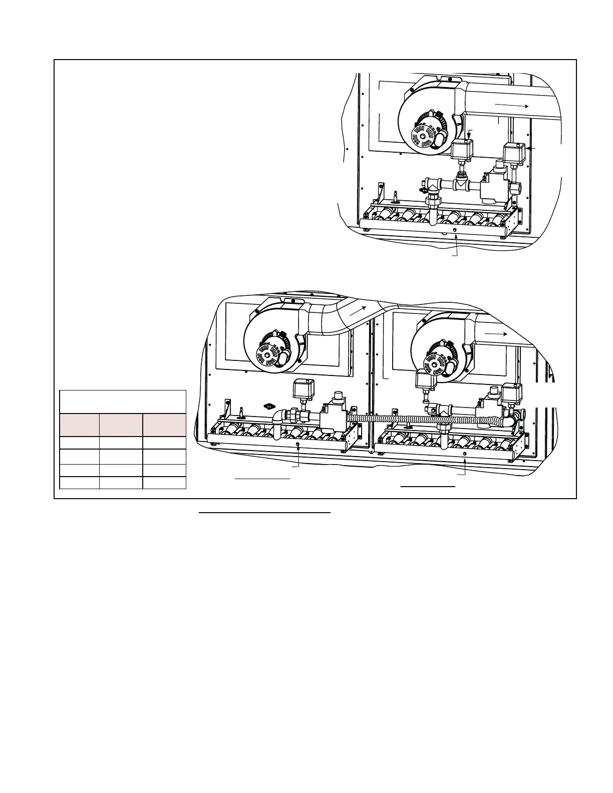
Flue
Collection
Box
Venter
Assembly
Single Heat Section
Manifold Assembly with
2-Stage Option AG71
Optional
Low Gas
Pressure
Switch
Optional
High Gas
Pressure
Switch
2-Stg
Gas
Valve
Ignitor
Limit
Manifold Pressure Tap
Optional High Gas
Pressure Switch
Ignitor
Limit
Venter
Assembly
Dual Heat Section
Manifold Assembly
with 4-Stage
Option AG72
Manifold Pressure Tap
Heat Section 2
Manifold Pressure Tap
Heat Section 1
Venter
Assembly
2-Stg
Valve
Optional
High Gas
Pressure
Switch
2-Stg
Valve
Optional Low
Gas Pressure
Switch
Ignitor
Limit
FIGURE 24 - Furnaces with
Staged Control Option AG71
(2-stage control, single heat
section) and Option AG72
(4-stage control, dual heat
sections)
NOTE: Heat sections
illustrated are standard
HI¿FLHQF\QRQFRQGHQVLQJ
IXUQDFHV&RQWUROVIRU
condensing furnaces are the
same.
Staging Sequence -
*DV&RQWURO2SWLRQ$*
Heat
Section
21
Stage 1 off /RZ¿UH
Stage 2 /RZ¿UH /RZ¿UH
Stage 3 /RZ¿UH +LJK¿UH
Stage 4 +LJK¿UH +LJK¿UH
5.1 Gas Heat Controls (cont'd)