Form O-Y, PN 273647R5, Page 34
Gas Control Modulating (5:1, Option AG73 or 10:1, Option AG74 - applies to all models)
Sequence of Operation
:LVHQHUJL]HGDQGWKH'6FRQWUROPRGXOHYHUL¿HVWKDWWKHSUHVVXUHVZLWFKHVDUHRSHQ
,QGXFHUYHQWHULVHQHUJL]HGIRUSUHSXUJHDQGWKH'6FRQWUROPRGXOHYHUL¿HVWKDWWKHORZDQGKLJKSUHVVXUH
switches are closed.
3) After the pre-purge period has elapsed (20 seconds), the DS1 control module energizes the trial for ignition period
(17 seconds).
$IWHUEORZHURQGHOD\VHFRQGVIURPÀDPHGHWHFWHG, the control will energize the blower (supply fan).
5) If W2 is energized, the high gas output will energize and the control will check for high pressure switch input.
6) After W1 and W2 are de-energized, the controller will run the blower-off delay (120 seconds) and return to standby
mode.
NOTE: For detailed information on the sequence of operation for the heat sections, refer to section 3.5 Heating
6WDJLQJ&RQWUROLQWKH0RGHO<'6$DQG<'+$0DQXDOIRU6SDFH7HPSHUDWXUH&RQWURO6\VWHP2SWLRQV'IRUP
&3<'RURSWLRQ'IRUP&3<'
Venter
Assembly
Optional High Gas
Pressure Switch
Ignitor
Limit
Dual Heat Section
Manifold Assembly
with Electronic
Modulation
Option AG74
Manifold Pressure Tap
Heat Section 2
2-Stg
Valve
Venter
Assembly
Optional
High Gas
Pressure
Switch
Manifold Pressure Tap
Heat Section 1
1-
Stg
Valve
Modulating
Valve
Venter Control
Pressure Switch
Optional
Low Gas
Pressure
Switch
Optional
Low Gas
Pressure
Switch
Optional High Gas
Pressure Switch
Ignitor
Venter
Assembly
Manifold Pressure Tap
Optional
Low Gas
Pressure
Switch
1-Stg
Valve
Modulating Valve
Venter
Control
Pressure
Switch
Single Heat
Section Manifold
Assembly with
Electronic
Modulation
Option AG73
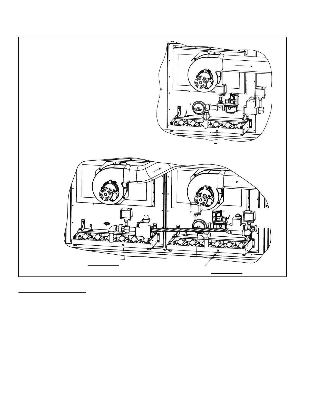
FIGURE 25 - Furnaces with
Modulating Control Option
AG73 (5:1 control, single
heat section) and Option
AG74 (10:1 control, dual
heat sections)
NOTE: Heat sections
illustrated are standard
HI¿FLHQF\QRQFRQGHQVLQJ
IXUQDFHV&RQWUROVIRU
condensing furnaces are the
same.
5.0 Maintenance/Service Procedures - Gas Heat Section (cont'd)
5.1 Gas Heat Controls (cont'd)