Form O-Y, PN 273647R5, Page 36
Depending on the heat section and gas control selected, all gas trains have one or
two single-stage and/or two-stage combination gas valves. These gas valves must
be checked annuallyWRHQVXUHWKDWWKH\DUHVKXWWLQJRIIJDVÀRZFRPSOHWHO\IROORZ
the instructions below.
Instructions:
1. /RFDWHWKH137SUHVVXUHWDSVRQWKHFRPELQDWLRQJDVYDOYH
2. Check the Manual Gas Valve - With the manual valve turned off to prevent
ÀRZWRWKHJDVYDOYHFRQQHFWDPDQRPHWHUWRWKH´LQOHWSUHVVXUHWDSLQWKH
combination valve. NOTE: A digital manometer is recommended.
:LWKWKH¿HOGLQVWDOOHGPDQXDOYDOYHUHPDLQLQJFORVHG¿UHWKHXQLWRQ7HVWPRGH
allow the unit to go through one trial for ignition. Turn off and observe the manom-
eter for two to three minutes for an indication of gas pressure. No pressure should
be indicated on the manometer.
If the manometer indicates a gas pressureWKH¿HOGLQVWDOOHGPDQXDOJDVYDOYH
must be replaced or repaired before the combination gas valve can be checked.
3. Check the Combination Valve - If the manometer does not indicate gas
pressureVORZO\RSHQWKHWHVWHG¿HOGLQVWDOOHGPDQXDOJDVYDOYH$IWHUWKH
manometer's indicated gas pressure has reached equilibrium, close the manual
shutoff valve. Observe the gas pressure. There should be no loss of gas pressure
on the manometer. If the manometer indicates a loss of pressure, replace the
combination gas valve before placing the heater in operation.
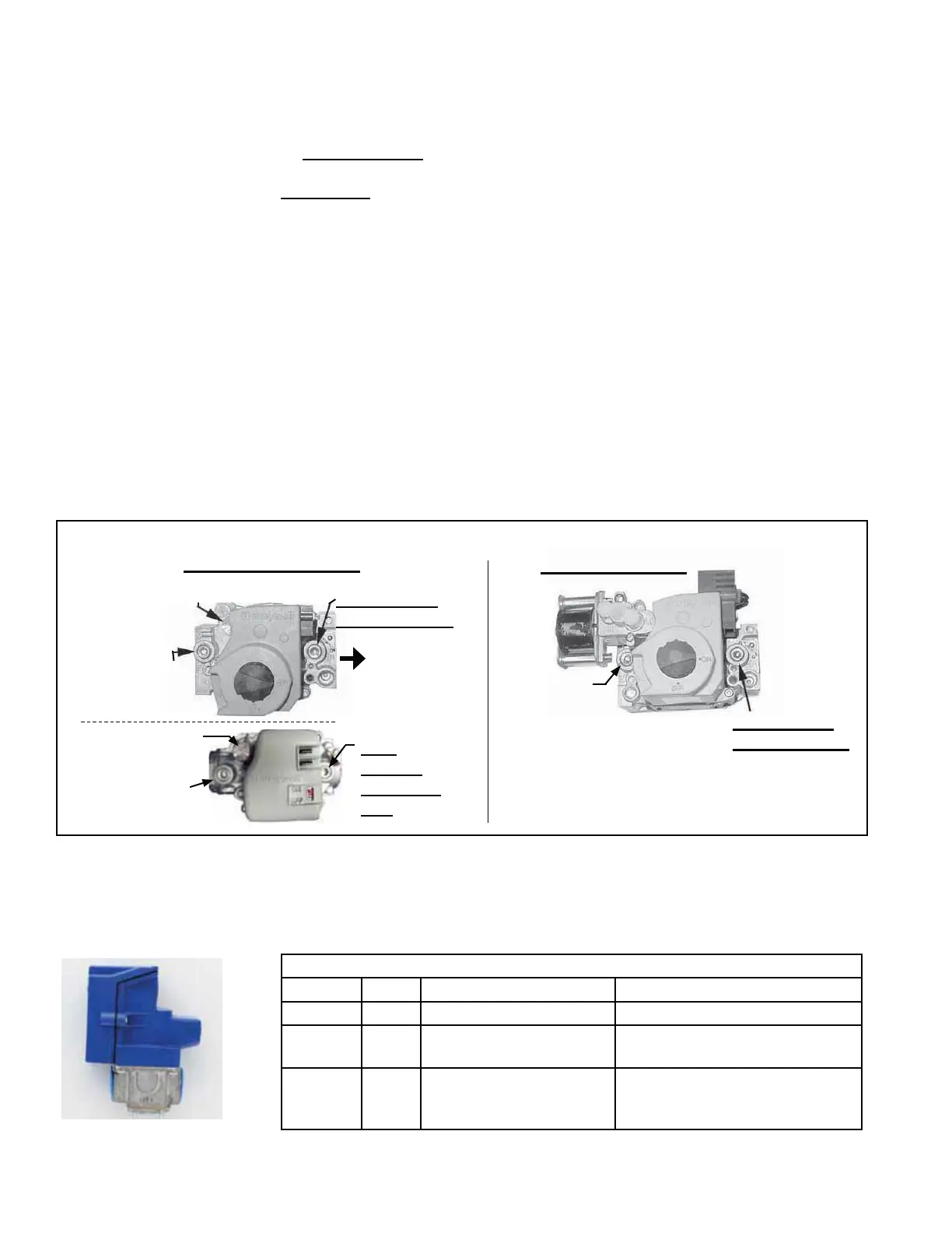
Operating Gas Valve -
Modulating Valve -
in Modulating Gas
Control Options
AG73 and AG74
Function:7KHPRGXODWLQJYDOYHUHVSRQGVWRWKHWR9'&VLJQDOIURPWKHFRQWURO-
ler to modulate the gas pressure to the burner.
Service:7KHPRGXODWLQJJDVYDOYHKDVQR¿HOGPDLQWHQDQFHUHTXLUHPHQWVH[FHSW
careful removal of external dirt accumulation and checking wiring connections.
FIGURE 26 - Top View of Two Types of Single-Stage Gas Valves and a Two-Stage Valve
1/8” Output
Pressure Tap
Inlet
Pressure Tap
Adjust Outlet
Pressure
1/8”
Output
Pressure
Tap
Inlet Pressure
Tap
Adjust Outlet
Pressure
1/8” Output
Pressure Tap
Inlet
Pressure
Tap
Two-Stage Valve
Single-Stage Valves
Modulating Valve in Options AG73 and AG74
Part No Size Single Heat Section Dual Heat Sections
273587 1/2" +++ +++++
271840 1/2"
*+
H300 (propane)
*++SURSDQH
H602 (propane)
273588 3/4"
G225 (natural),
G300 (natural),
+QDWXUDO+
G372 (natural), G452 (natural),
G525, G602, H502 (natural),
+QDWXUDO++
5.0 Maintenance/Service Procedures - Gas Heat Section (cont'd)
5.1 Gas Heat Controls (cont'd)