Form O-Y P/N 273647R5, Page 37
&RQGHQVDWH'UDLQ+LJK(I¿FLHQF\+HDW6HFWLRQ
&KHFNWKHFRQGHQVDWHGUDLQ
&OHDQWKHGUDLQDQGWUDS
1. Open the cleaning ports and use the brush provided to clean the drain.
2. 7RFOHDQWKHWUDSDQGÀRDWXQVFUHZWKHUHWDLQLQJULQJDQGUHPRYHWKHERWWRP
VHFWLRQRIWKHWUDS5HPRYHWKHÀRDWDQGVSULQJ&OHDQWKHSDUWVZLWKVRDS\ZDWHU
3. 5HDVVHPEOHWKHWUDSE\LQVHUWLQJWKHVSULQJDQGÀRDWLQWRWKHERWWRPWUDSVHFWLRQ
Position the bottom section in to the top and secure with the retaining ring.
4. 5HFRQQHFWWKHWUDSDQGFKHFNIRUSURSHUÀRZ
Condensate Drain Pressure Switch (See FIGURE 23, page 32)
Function: If the condensate drain is blocked causing the sensing pressure to be
outside the switch setpoint, the pressure switch will shutoff the gas valve. The gas
valve will remain off until the problem is corrected.
Service: If it is determined that the condensate pressure switch needs replacing,
use only a factory-authorized replacement part that is designed for the heater. See
FIGURE 23, page 32 for location.
Condensate Drain
Pressure Switch
5.2 Combustion Air
and Venting
Combustion Air
Proving Switch (see
table on page 38)
The gas heat section is power vented. Presence of combustion air pressure is moni-
tored by a combustion air proving switch located in the heat section.
The combustion air proving switch is a pressure sensitive switch that monitors air
pressure to ensure that proper combustion air is available. The switch is single pole/
VLQJOHWKURZZLWKWKHQRUPDOO\RSHQFRQWDFWVFORVLQJZKHQWKHSURSHUDLUÀRZLV
sensed in the system.
On start-up when the heater is cold, the sensing pressure is at the most negative
OHYHODQGDVWKHKHDWHUDQGÀXHV\VWHPZDUPXSWKHVHQVLQJSUHVVXUHEHFRPHV
less negative. After the system has reached equilibrium (about 20 minutes), the sens-
ing pressure levels off.
If a restriction causes the sensing pressure to be outside the switch setpoint, the
pressure switch will function to shut off the main burners. The main burners will
UHPDLQRIIXQWLOWKHV\VWHPKDVFRROHGDQGRUWKHÀXHV\VWHPUHVLVWDQFHLVUHGXFHG
The table on page 38 lists the approximate water column negative pressure readings
and switch set points for sea level operating conditions.
DANGER
6DIHRSHUDWLRQUHTXLUHVSURSHUYHQWLQJÀRZ1HYHUE\SDVVWKH
combustion air proving switch or attempt to operate the heat
VHFWLRQZLWKRXWWKHYHQWHUUXQQLQJDQGSURSHUÀRZLQWKHYHQW
system. Hazardous condition could result.
Service: if the pressure switch needs to be replaced, use a factory-authorized
replacement designed for the application.
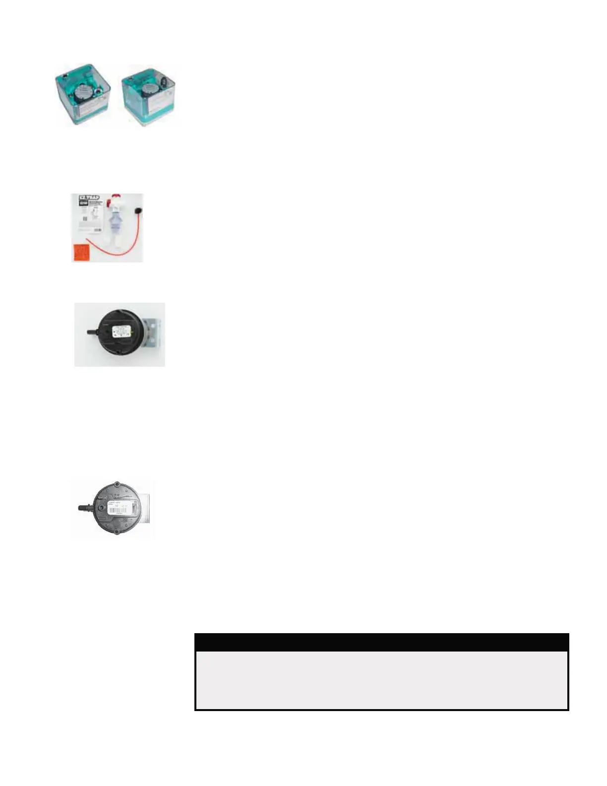
Optional Gas
Pressure Switches
Location: /RZSUHVVXUHVZLWFKLVDWWKHHQWUDQFHWRWKHJDVWUDLQ7KHKLJKSUHVVXUH
switch is at the burner end. See FIGURE 24, page 33 or 25, page 34.
Function: Monitors gas pressure and shuts down the heat section if gas pressure
becomes too low or too high. The low pressure switch is an auto reset type and is set
DWRIWKHPD[LPXPPDQLIROGSUHVVXUH7KHKLJKSUHVVXUHVZLWFKUHTXLUHVPDQXDO
UHVHWDQGLVVHWDWRIPDQLIROGSUHVVXUH
Service: There are no replaceable parts and the settings are non-adjustable. If
replacement is required, use identical factory-authorized safety switches.
Low
P/N 204375
High
P/N 204279
P/N 234712
Set Point 0.10 I.W.C.
Condensate Drain
Trap P/N 271064