25
TM061 Rheem 27 Water Star Service Instructions – Issued: 11/10
REV A Issued 08/13
This document is stored and maintained electronically by Service. All printed copies not bearing this statement in RED are deemed “uncontrolled”
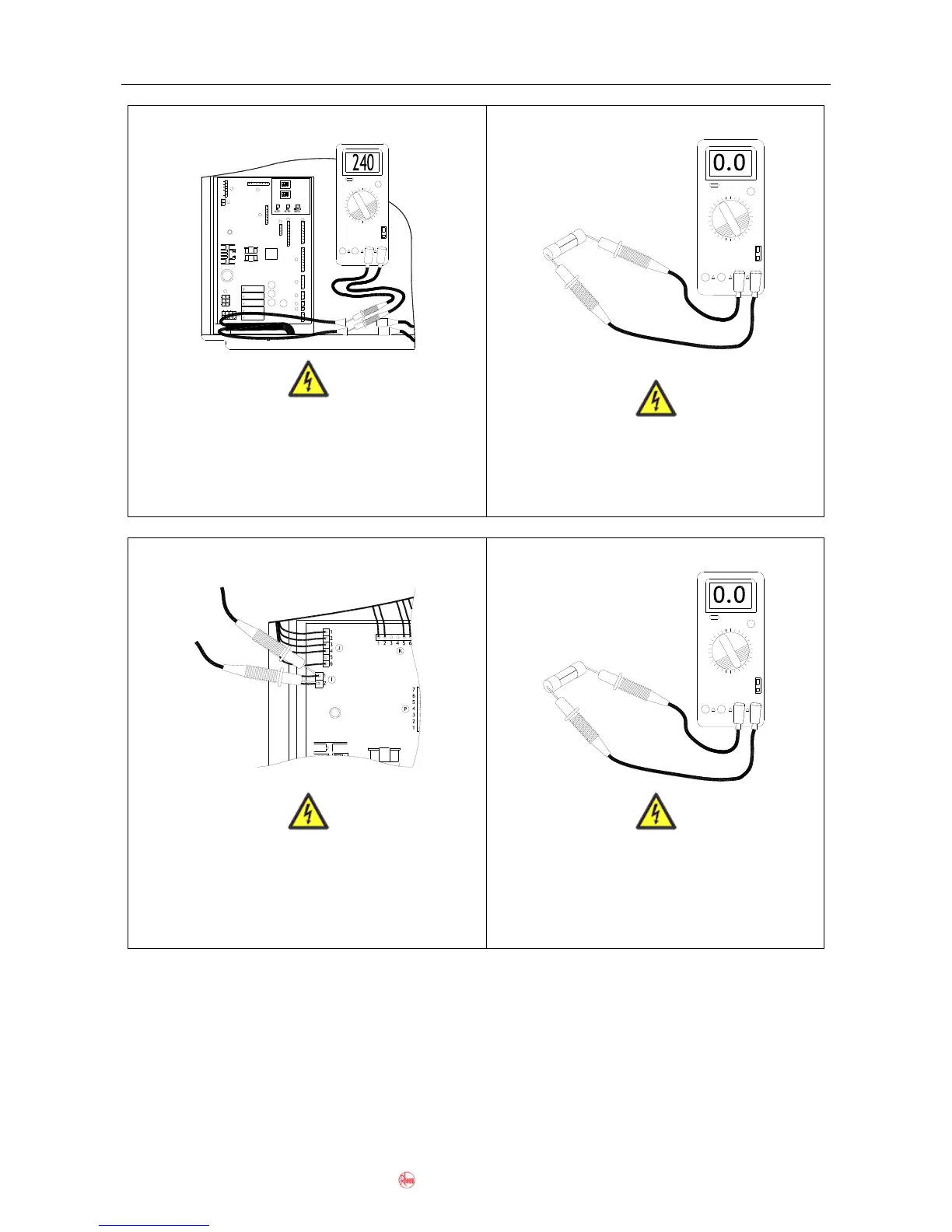
Fault-Finding Tests 1 - 4
Using a multimeter set on the AC volts scale,
measure the voltage between the blue and
brown wires at the inline fuse connectors.
Normal voltage is between 216 and 264VAC.
Using a multimeter set on the resistance
scale, measure across each 5A fuse.
Resistance should be 0 ohms.
Using a multimeter set on the DC volts scale,
measure the voltage between red and grey wires
at terminal I on the control PCB.
Normal voltage is between 144V and 192V DC.
Using a multimeter set on the resistance
scale, measure across the 5A fuse.
Resistance should be 0 ohms.
12VDC JAPAN
G5NB-1A4
OMRON
12VDC JAPAN
G5NB-1A4
OMRON
12VDC JAPAN
G5NB-1A4
OMRON
OMRON
G5NB-1A4
12VDC JAPAN
12VDC JAPAN
G5NB-1A4
OMRON
Q
9
5
6
7
8
1
2
3
4
4
3
2
1
5
R
1
2
3
S
2
1
T
1
U
1
2
3
V
X
3
1
25
4
6
W
1
5 6 7
8
432
1
2
3
4
4
3
2
1
8
7
6
5
N
O
9
M
5
6
7
8
1
2
3
4
SW1 SW2 SW3
DIP1
1 2 34
ON
OFF
OFF
ON
4321
DIP2
4
3
2
1
7
6
5
P
K
1 2 3 4 5 6 87
2
1
I
1
J
2
3
4
5
6

 Loading...