27
F
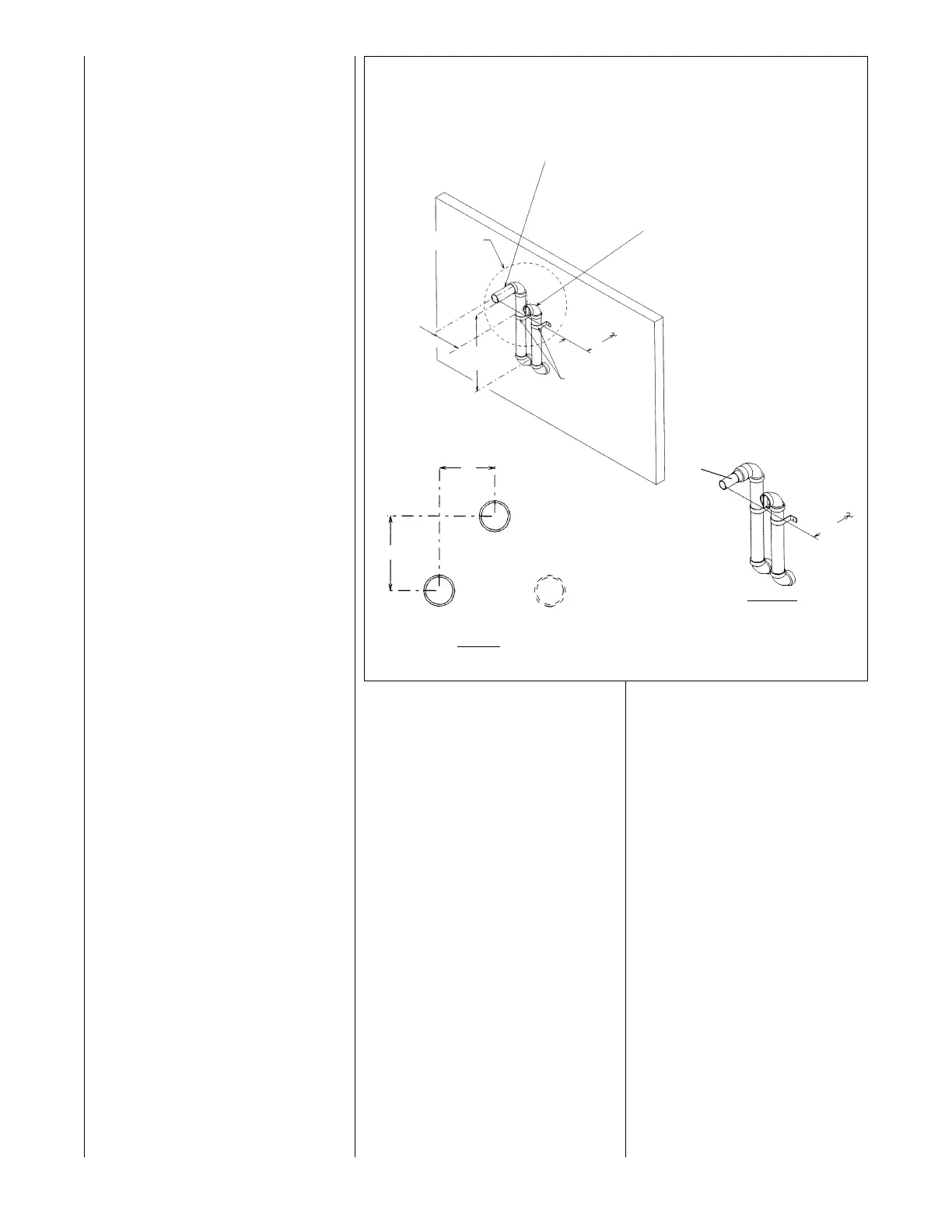
IGURE 18
ALTERNATE HORIZONTAL DIRECT VENT TERMINATION
• Insulate the entire length of vent
pipe, between the elbow where the
pipe exits the wall and the elbow
where the termination is made, with
a
closed-cell insulation, such as
“
Arm-a-Flex” or “Rub-a-Tex” with a
minimum of 1/2” thickness.
• All elbows installed on the exterior
of the building must be of the long
sweep nature.
• As required for the horizontal piping
ran within the structure, any pipe
ran horizontal outside the structure
must slope upward a minimum of
1/4” per foot run so that condensate
drains toward the furnace.
From the top elbow in the exhaust
pipe, extend a length of PVC pipe
outward so that it terminates exactly
12 inches from the wall. See Figure
18. Reduce the termination pipe
extension to is 1
1
/2 inch pipe for
45,000 BTUH through 75,000 BTUH
units.
The 45,000 BTUH unit only uses kit
RXGY-D02. The 60,000 BTUH and
75,000 BTUH units may use kits
RXGY-D02 or RXGY-D03 depending
on pipe lengths and number of
elbows. Use kit RXGY-D03 with
90,000 BTUH through 120,000 BTUH
units. The RXGY-D04 kit only
applies to the 120,000 BTUH unit
using an alternate termination and
long runs. See Table 2.
The following are parts lists for the
RXGY-D02, RXGY-D03 and RXGY-
D04 alternate horizontal direct vent
termination kits:
RXGY-D02
1. 2-in. tee with reducer assembly
2.
1
/2-in. PVC 6-in. dia. trap
3. PVC vane
4. 2-in. PVC elbow
5. 1
1
/2-in. PVC nipple with coupling
6. PVC strap
7. vent template
RXGY-D03
1. 3-in. tee with reducer assembly
2.
1
/2-in. PVC 6-in. dia. trap
3. PVC vane
4. 2-in. PVC elbow
5. PVC strap
6. vent template
RXGY-D04
1. 2
1
/2-in. PVC elbow
2. 3" x 2
1
/2" PVC bushing
3. 2
1
/2" x 6
1
/2" long PVC pipe
4. 2
1
/2" x 16" long PVC pipe
5. 2
1
/2" x 21" long PVC pipe
6. PVC vane
7.
3-in. tee with reducer assembly
8. 6-in. dia.
1
/2-in. PVC trap
9. PVC strap
10. vent template
NOTE: The RXGY-D04 kit only
applies to the 120,000 BTUH unit
using an alternate termination and
excessively long runs.
S
EE DETAIL A
6
0” MAX.
P
IPE
S
UPPORT
S
TRAP
3” MAX.
NOTE: 3-1/2”
M
AX. WHEN
D04 KIT IS
U
SED.
EXHAUST VENT
2
1
/2" PVC FOR MODELS WITH 120,000 BTU INPUT
(KIT NO. RXGY-D04)
2" PVC FOR MODELS WITH INPUTS OF 90,000 AND
120,000 BTU. REDUCE TO 1
1
/2" FOR MODELS WITH
INPUTS OF 45,000 THRU 60,000 BTU (SEE DETAIL A).
ELBOWS AND RISERS ARE 2" PVC.
I
NTAKE VENT
2
1
/2"
PVC FOR MODELS WITH
1
20,000 BTU INPUT.
2" PVC ELBOWS AND RISER
MODELS WITH INPUTS OF 45,000
THRU 120,000 BTU.
USE KIT NO. RXGY-D02 WHEN 2" PIPE
IS USED BETWEEN FURNACE AND
OUTSIDE WALL. USE KIT NO. RXGY-D03
WHEN 3" PIPE IS USED.
I339
1
2
”
F
R
OM
WA
L
L
3”
4”
EXHAUST
INTAKE
OPTIONAL
INTAKE
DETAIL B
EXHAUST / INTAKE RELATIONSHIP
DETAIL A
EXHAUST VENT FOR
MODELS WITH
I
NPUT OF 45,000 THRU
60,000 BTU
1
2
”
FR
O
M
WA
LL
1
1
/2” PIPE
 Loading...