EasyManua.ls Logo

Rheem AdvantagePlus HE119-199N User Manual

Rheem AdvantagePlus HE119-199N
30 pages
To Next Page IconTo Next Page
Page #1 background imageLoading...
Page #1 background image
High Efficiency Commercial Gas Water Heater
USE & CARE MANUAL
WITH INSTALLATION INSTRUCTIONS FOR THE CONTRACTOR
ON
OFF
This Use & Care Manual covers the following model numbers:
HE45-100N HE119-130N HE45-199LP
HE45-130N HE119-160N HE80-130LP
HE45-160N HE119-199N HE80-160LP
HE45-199N HE80-199LP
HE80-130N HE45-100LP HE119-130LP
HE80-160N HE45-130LP HE119-160LP
HE80-199N HE45-160LP HE119-199LP
NOTICE: This water heater is designed for use in a commercial application. The installation and
maintenance of it should be performed by qualified, licensed service personnel.
!
CALIFORNIA PROPOSITION 65 WARNING: This product contains chemicals known to the State of California
to cause cancer, birth defects or other reproductive harm.
!
AP12158-2 (04/05)
Printed in the USA
FOR YOUR SAFETY!
Do not store or use gasoline or other flammable
vapors or liquids or other combustible materials in
the vicinity of this or any other appliance.To do so
may result in an explosion or fire.
WHAT TO DO IF YOU SMELL GAS
Do not try to light any appliance.
Do not touch any electrical switch; do not use any
phone in your building.
Immediately call your gas supplier from a neigh-
bor's phone. Follow the gas supplier's instruc-
tions.
If you cannot reach your gas supplier, call the fire
department.
Do not return to your building until authorized by
the gas supplier or fire department.
Improper installation, adjustment, alteration, ser-
vice or maintenance can cause injury, property
damage or death. Refer to this manual. Installation
and service must be performed by a qualified
installer, service agency or the gas supplier.
WARNING: If the information in these instructions are not followed exactly, a fire or explosion may result
causing property damage, personal injury or death.
!
!
Do Not Destroy this Manual. Please read carefully
and keep in a safe place for Future Reference.
Recognize this symbol as an Indication of Important
Safety Information!
!
!
WARNING: Read and review this entire manual with special emphasis on the Venting and Operation
Sections prior to any installation work.
!
Question and Answer IconNeed help?

Do you have a question about the Rheem AdvantagePlus HE119-199N and is the answer not in the manual?

Rheem AdvantagePlus HE119-199N Specifications

General IconGeneral
CategoryWater Heater
BrandRheem
ModelAdvantagePlus HE119-199N
Capacity119 gallons
Energy Factor0.95 UEF
Height76 inches
Fuel TypeNatural Gas
Vent TypePower Vent
Warranty6 years
Input Rating199, 000 BTU/hr

Summary

Safety First

Important Safety Symbols and Warnings

Highlights safety symbols, manual importance, and general warnings for safe operation.

Specific Safety Precautions

Covers warnings about flammable liquids, gas leaks, and basic safety steps.

Product Specifications

Recovery Capacities and Delivery

Details water recovery rates and maximum delivery volumes across various models and conditions.

Dimensional Information

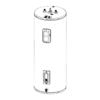
Provides physical dimensions in English and Metric units for different models.

General Safety Guidelines

Flammable Materials and Gas Hazards

Warns against flammable materials, LP gas risks, and procedures for detecting gas leaks.

Venting and Air Supply Safety

Emphasizes risks of improper venting and lack of air supply, including carbon monoxide dangers.

Temperature Safety and Fuel Types

Water Temperature Scald Hazards

Warns about high water temperatures causing burns and provides scald data.

Fuel Type Compliance

Stresses using correct fuel types and avoiding conversions between natural gas and LP.

Installation Essentials

Regulatory and Location Requirements

Covers local codes, national standards, and suitable location criteria for installation.

Key Component Installation

Details installation of the Temperature & Pressure Relief Valve and Expansion Tank.

Installation Details

Water and Booster Connections

Guides on domestic water connections and installing the booster kit.

Electrical and Gas Connections

Outlines requirements for electrical hookup, gas supply, and leak testing.

Venting with 3" Pipe

3" Vent Pipe Requirements

Specifies materials, slopes, lengths, and clearances for 3" vent systems.

Venting Guidelines and Fittings

Provides clearance rules for vent terminals and details compatible pipe/fitting materials.

Venting with 2" Pipe and Setup

2" Vent Pipe and Longer Venting

Covers 2" vent pipe rules and methods for extending vent length using larger pipes.

Setup and Combustion Analysis

Offers setup instructions and combustion analyzer readings for optimal performance.

Venting Technical Data

Friction Loss and Venting Examples

Presents tables for calculating vent pipe friction loss and examples of vent length calculations.

Operation and Controls

Control System Overview

Describes the electronic control, its diagnostics, and startup procedures.

Temperature Set Point Adjustment

Guides users on how to set and adjust the desired water temperature.

Operational Procedures

Thermostat Differential and Operation Sequence

Explains thermostat settings, normal operation sequence, and status indicators.

Maintenance and Shutdown Procedures

Covers routine maintenance, shutdown, and vacation procedures.

Operation and Troubleshooting

Failure Modes and Fuel Conversions

Addresses operational failures, lockout states, and fuel conversion information.

Condensate Management

Explains the condensate system, treatment, and potential issues.

Component Identification

AdvantagePlus Components Diagram

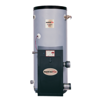
Provides a labeled diagram of the water heater's internal components.

Gas Valve Adjustment and Troubleshooting Basics

Gas Valve Adjustment

Details procedures for adjusting the gas valve for proper ignition and flame.

Troubleshooting Overview

Introduces the control system's diagnostic features and LED indicators.

Status Indicators: Initial States

Idle, Call for Heat, and Blower States

Describes LED indicators for the idle, call for heat, and combustion blower powered states.

Status Indicators: Operational Phases

Ignition and Heating Status

Details LED indicators during pre-purge, igniter warmup, burner ignition, and water heating.

End of Cycle Status

Explains LED indicators at the end of the heating cycle and when returning to idle state.

Troubleshooting: Power and Ignition Issues

No Voltage or 24V Status

Covers causes and remedies for missing line voltage or 24VAC from the transformer.

Ignitor Lockout Status

Explains the LED indicators for ignitor lockout and potential issues.

Troubleshooting: Ignition Lockout and ECO Switch

Ignition Lockout: Gas Valve LED

Details causes for ignition lockout indicated by the gas valve LED and troubleshooting steps.

ECO Switch Open Status

Describes causes for the ECO switch LED flashing and necessary actions.

Troubleshooting: Control and Sensor Faults

Control Health LED Status

Explains the meaning of the Control Health LED flashing and troubleshooting steps.

Combustion and Temperature Probe Faults

Covers causes for combustion air blockage and temperature probe faults indicated by LEDs.

Control Wiring Diagram

Integrated Control Connection Diagram

Shows the detailed wiring connections for the water heater's integrated control system.

Parts Identification

Control System Parts Identification

Provides a list and visual guide for identifying control system components.

Venting Setup Diagrams

Side and Vertical Venting Configurations

Illustrates side and vertical roof venting setups with critical clearances and pipe types.

Venting Samples

Venting Configurations and Kits

Shows various side wall and vertical roof venting samples, including the V1000 vent kit.

Piping Diagrams

Piping for Storage Tank Models

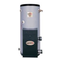
Displays sample manifold and piping diagrams for AdvantagePlus units with storage tanks.

Sequence of Operations: Startup

Initial Power-On and Diagnostics

Details the initial steps upon powering the unit, including diagnostic checks.

Call for Heat and Pre-Purge

Explains the sequence when the thermostat calls for heat and the pre-purge cycle starts.

Sequence of Operations: Heating and Shutdown

Igniter, Burner Ignition, and Heating

Describes the process from igniter warmup through burner operation to water heating.

Post-Purge and Idle State

Covers the post-purge cycle and the unit returning to its idle state.

Display Board LED Indicators

LED Functions and Troubleshooting

Explains each LED's function, possible causes for faults, and service remedies.

General Troubleshooting Guide

Troubleshooting Common Issues

Lists common problems (e.g., no hot water, noise, leaks) with causes and service solutions.

Obtaining Technical Assistance

Provides guidance on contacting support for service and technical assistance.

Common Installation Concerns

Venting, Gas, and Electrical Issues

Highlights frequent installation problems related to venting, gas supply, and electrical grounding.

Plumbing, Condensate, and Burner Issues

Covers common installation concerns for plumbing, condensate removal, and burner operation.

Related product manuals