EasyManua.ls Logo

Rheem AdvantagePlus HE119-160N User Manual

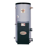
Rheem AdvantagePlus HE119-160N
30 pages
To Next Page IconTo Next Page
Page #1 background imageLoading...
Page #1 background image
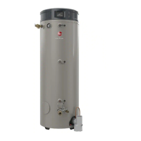
High Efficiency Commercial Gas Water Heater
USE & CARE MANUAL
WITH INSTALLATION INSTRUCTIONS FOR THE CONTRACTOR
ON
OFF
This Use & Care Manual covers the following model numbers:
HE45-100N HE119-130N HE45-199LP
HE45-130N HE119-160N HE80-130LP
HE45-160N HE119-199N HE80-160LP
HE45-199N HE80-199LP
HE80-130N HE45-100LP HE119-130LP
HE80-160N HE45-130LP HE119-160LP
HE80-199N HE45-160LP HE119-199LP
NOTICE: This water heater is designed for use in a commercial application. The installation and
maintenance of it should be performed by qualified, licensed service personnel.
!
CALIFORNIA PROPOSITION 65 WARNING: This product contains chemicals known to the State of California
to cause cancer, birth defects or other reproductive harm.
!
AP12158-2 (04/05)
Printed in the USA
FOR YOUR SAFETY!
Do not store or use gasoline or other flammable
vapors or liquids or other combustible materials in
the vicinity of this or any other appliance.To do so
may result in an explosion or fire.
WHAT TO DO IF YOU SMELL GAS
Do not try to light any appliance.
Do not touch any electrical switch; do not use any
phone in your building.
Immediately call your gas supplier from a neigh-
bor's phone. Follow the gas supplier's instruc-
tions.
If you cannot reach your gas supplier, call the fire
department.
Do not return to your building until authorized by
the gas supplier or fire department.
Improper installation, adjustment, alteration, ser-
vice or maintenance can cause injury, property
damage or death. Refer to this manual. Installation
and service must be performed by a qualified
installer, service agency or the gas supplier.
WARNING: If the information in these instructions are not followed exactly, a fire or explosion may result
causing property damage, personal injury or death.
!
!
Do Not Destroy this Manual. Please read carefully
and keep in a safe place for Future Reference.
Recognize this symbol as an Indication of Important
Safety Information!
!
!
WARNING: Read and review this entire manual with special emphasis on the Venting and Operation
Sections prior to any installation work.
!
Question and Answer IconNeed help?

Do you have a question about the Rheem AdvantagePlus HE119-160N and is the answer not in the manual?

Rheem AdvantagePlus HE119-160N Specifications

General IconGeneral
BrandRheem
ModelAdvantagePlus HE119-160N
CategoryWater Heater
LanguageEnglish

Summary

SPECIFICATIONS

RECOVERY CAPACITIES

Recovery rates in GPH and LPH at various temperature rises.

BOOSTER MODELS

Recovery rates for booster models in GPH and LPH.

MAXIMUM DELIVERY

Water delivery volumes in gallons and liters over time.

DIMENSIONAL INFORMATION

Physical dimensions and connection sizes in English and Metric.

General Safety Precautions

INSTALLATION

LOCAL INSTALLATION REGULATIONS

Requirements for installing the water heater according to codes.

LOCATION

Guidance on choosing a suitable installation location.

TEMPERATURE AND PRESSURE RELIEF VALVE

Requirements for installing the T&P relief valve.

EXPANSION TANK

Explanation of the need for an expansion tank.

INSTALLATION

DOMESTIC WATER CONNECTIONS

Instructions for connecting water supply and return lines.

SPECIAL INSTRUCTIONS FOR BOOSTER INSTALLATIONS

Specific guidance for installing booster kits.

VENTING WHEN USING 3" VENT PIPE

Venting Guidelines

Rules and recommendations for proper vent placement and clearances.

PIPE / FITTINGS WHEN USING 3" VENT PIPE

Specifications for PVC, ABS, and CPVC piping and fittings.

FOR LONGER VENT LENGTHS WHEN USING 3" VENT PIPE

Guidelines for extending vent lengths with larger diameter pipes.

VENTING WHEN USING 3" VENT PIPE

SPECIAL VENTING INSTRUCTIONS USING 2" VENT PIPE

Instructions for models using 2-inch vent pipe.

PIPE / FITTINGS WHEN USING 2" VENT PIPE

Specifications for 2-inch PVC, ABS, and CPVC piping.

FOR LONGER VENT LENGTHS WHEN USING 2" VENT PIPE

Guidelines for extending vent lengths with 3-inch pipes.

OPERATION

CONTROL DESCRIPTION

Overview of the electronic control system and its components.

START UP PROCEDURE

Step-by-step instructions for initial unit startup.

TEMPERATURE SET POINT ADJUSTMENT PROCEDURE

How to set the desired water temperature on the thermostat.

THERMOSTAT DIFFERENTIAL ADJUSTMENT PROCEDURE

OVERALL APPLIANCE AND CONTROL OPERATION

FAILURE TO OPERATE

FUEL CONVERSIONS

CORROSIVE ATMOSPHERES

CONDENSATE

COMPONENTS DIAGRAM

GAS VALVE ADJUSTMENT

TROUBLESHOOTING

STATUS INDICATIONS UNDER NORMAL CONDITIONS

STATUS INDICATIONS UNDER NORMAL OPERATING CONDITIONS

NO INCOMING LINE VOLTAGE OR 24 VOLT

IGNITOR LOCKOUT

IGNITION LOCKOUT

ECO SWITCH OPEN

CONTROL HEALTH

COMBUSTION AIR BLOCKAGE

TEMPERATURE PROBE FAULT

CONNECTION DIAGRAM

Parts Identification Drawing

VERY IMPORTANT SET-UP INSTRUCTIONS!

FIGURE 1 - SIDE VENTING

Diagram illustrating side venting configuration.

FIGURE 2 - SIDE VENTING

Diagram illustrating side venting configuration.

FIGURE 3 - VERTICAL ROOF VENTING

Diagram illustrating vertical roof venting configuration.

FIGURE 4 VERTICAL ROOF VENTING W/ CONCENTRIC VENT KIT

Diagram of vertical roof venting with a concentric kit.

Venting Samples

FIGURE 5 - SIDE WALL VENTING

Diagram of side wall venting with 3" and 4" pipe.

FIGURE 6 - VERTICAL ROOF VENTING

Diagram of vertical roof venting with 3" and 4" pipe.

FIGURE 7 - SIDE WALL VENTING USING THE V1000 VENT KIT

Diagram of side wall venting using a specific vent kit.

AdvantagePlus with Storage Tank

Sample Reverse Manifold and Piping Diagram

Diagram showing reverse manifold and piping for the AdvantagePlus.

Sequence of Operations

Display Board LEDs

LINE LED

Status of the LINE LED and its controlling function.

24 VAC LED

Status of the 24 VAC LED and its controlling function.

ECO/VENT SWITCH LED

Status of the ECO/VENT SWITCH LED and its function.

PRESSURE SWITCH LED

Status of the PRESSURE SWITCH LED and its function.

WATER TEMPERATURE LED

Status of the WATER TEMPERATURE LED and its function.

GAS VALVE LED

Status of the GAS VALVE LED and its function.

BLOWER LED

Status of the BLOWER LED and its function.

IGNITOR LED

Status of the IGNITOR LED and its function.

CONTROL HEALTH LED

Status of the CONTROL HEALTH LED and its function.

GREEN LED ON MAIN CONTROL BOARD

Status of the GREEN LED for ground and polarity.

Trouble Shooting Guide

No Hot Water

Troubleshooting steps for lack of hot water.

Not Enough Hot Water

Troubleshooting steps for insufficient hot water supply.

Water Too Hot

Troubleshooting steps for excessive hot water temperature.

Slow Hot Water Recovery

Troubleshooting steps for slow hot water recovery.

Noisy Water Heater

Troubleshooting steps for noise issues.

Excessive Relief Valve Operation

Troubleshooting steps for frequent relief valve operation.

Rusty Water

Troubleshooting steps for rusty water issues.

Water On Floor Around Unit

Troubleshooting steps for leaks or condensate issues.

Water heater is leaking

Troubleshooting steps for water leaks from the unit.

MOST COMMON ADVANTAGEPLUS INSTALLATION CONCERNS

VENTING

Common issues related to venting installation.

GAS SUPPLY

Common issues related to gas supply and pressure.

ELECTRICAL

Common issues related to electrical connections.

PLUMBING

Common issues related to plumbing connections.

CONDENSATE

Common issues related to condensate line and drainage.

BURNER

Common issues related to burner operation.

GAS VALVE

Common issues related to gas valve operation.

Related product manuals