Do you have a question about the Rheem RUUD AdvantagePlus and is the answer not in the manual?
Key initial checks before diagnosing AdvantagePlus unit issues.
Troubleshooting no 120VAC line voltage when the LINE LED is off.
Diagnosing issues based on the green LED status on the control board.
Troubleshooting when the 24 VAC LED is off, indicating transformer issues.
Verifying 24 VAC power supply from the transformer to the control board.
Diagnosing issues related to ECO, vent, and low water cut-off switches.
Checking ECO activation based on water temperature and T&P valve.
Testing continuity of the ECO/Temp probe for proper function.
Verifying activation and power to the low water cut-off switch.
Testing continuity of the low water cut-off switch for proper operation.
Diagnosing issues related to PVC venting and the pressure switch.
Testing the pressure switch for correct operation and continuity.
Verifying 120VAC power supply to the combustion blower motor.
Checking for DC control voltage signal to the blower motor from the board.
Reviewing venting installation parameters for proper combustion air flow.
Ensuring proper termination, pitch, and support for venting system.
Diagnosing gas valve issues related to flame rectification and ignition attempts.
Testing for 24VAC power to the gas valve and its proper operation.
Checking gas pressure and fuel supply adequacy for unit operation.
Evaluating utility meter capacity and appliance regulator setup for gas supply.
Proper sizing and installation of appliance regulators for gas supply.
Verifying 120VAC power is applied to the igniter for ignition.
Checking igniter circuit amp draw to ensure proper ignition operation.
Verifying power supply to the combustion blower motor.
Tracing 120VAC power path from the control board to the blower motor.
Verifying the DC control signal path from the control board to the blower.
Checking water temperature probe resistance for accurate tank temperature readings.
Troubleshooting control board self-diagnosis errors and reset procedures.
Diagnosing main burner lockout after multiple failed ignition attempts.
Identification and part numbers for replacement components of the control system.
Detailed wiring diagram showing connections between control board and components.
Chart providing resistance values for the thermistor at various temperatures.
This document outlines troubleshooting procedures for the Rheem/Ruud AdvantagePlus water heater, focusing on various operational and diagnostic aspects. It serves as a guide for technicians to identify and resolve common issues, ensuring the unit operates efficiently and safely.
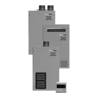
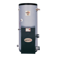
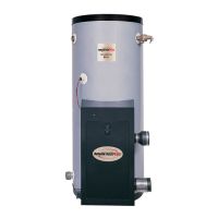
The AdvantagePlus water heater is designed to provide hot water, incorporating several safety and control features. Its core function involves heating water and maintaining it at a set temperature, while continuously monitoring various parameters to ensure safe operation. The unit utilizes a control board that integrates multiple sensors and relays to manage the heating process, combustion, and safety interlocks.
Key operational components include:
The AdvantagePlus water heater is designed for user-friendly operation with built-in diagnostic capabilities to assist in troubleshooting.
The design of the AdvantagePlus water heater and its diagnostic tools facilitate maintenance and repair.
Overall, the AdvantagePlus troubleshooting guide emphasizes a systematic approach to diagnosis, leveraging the unit's built-in indicators and requiring standard electrical and plumbing measurement tools to ensure safe and effective resolution of operational issues.
| Category | Water Heater |
|---|---|
| Brand | Rheem RUUD |
| Series | AdvantagePlus |
| Fuel Type | Natural Gas / Propane |
| Vent Type | Atmospheric |
| Warranty | 6 years |