Do you have a question about the Rheem GHE80-300 and is the answer not in the manual?
Describes the integrated control system for GHE water heaters.
Highlights dangers of electrical shock during service and repairs.
Warns against storing or using flammable materials near the water heater.
Advises on safe water temperature settings to prevent scalding.
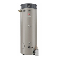
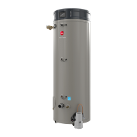
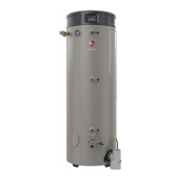
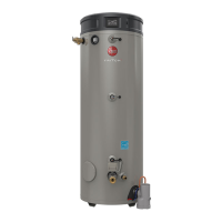
Details GHE models, gallon capacity, and fuel types.
Covers rated gas input and ignition system details.
Describes the heat exchanger type and diagnostic capabilities.
Outlines installation requirements and connection types.
Details allowed vent materials and noise level standards.
Covers water temperature settings, differential, and electrical rating.
Lists safety devices like T&P valve and ECO switch.
Provides minimum, maximum, and ignition speeds for models.
Specifies purge timing in seconds for various models.
Identifies components visible from the top view.
Illustrates and names major components on the main unit.
Details components of the burner assembly.
Shows the block diagram for the gas high efficiency system.
Illustrates connections for pressure and temp sensors.
Details connections to the control board.
Identifies key components visible from the top.
Describes the blower and gas control valve functions.
Explains the flue gas temperature sensor and its trip setting.
Details the power anode controller's role in tank protection.
Describes the condensate trap and igniter/flame probe.
Explains the main igniter controller's operations and attempts.
Describes the touch screen interface and its display.
Details the function of pressure switches.
Explains the function of temperature probes.
Describes the leak sensor and burner functions.
Explains how to navigate the main display screen.
Describes the initial setup process via the wizard.
How to turn the water heater on or off.
Details how to adjust water temperature settings.
Configuration options for display, lock, beep, and network.
Settings for differential temp, pump, input/output, modulation, leak.
How to set heater schedules for use.
How to set the current time and daylight savings.
Provides current status, diagnostics, sensors, and more details.
Accesses product info, alarms, system health, and alerts.
Checking and configuring the water heater's Wi-Fi connection.
Viewing active alarms, history, and more information.
Checking combustion and tank health status.
Setting reminders for maintenance tasks.
Explains various status messages displayed on the control board.
Describes the initial steps for a heat demand.
Details the pre-purge cycle operations.
Checks performed during flame stabilization.
Describes heating mode and responses to flame loss.
Explains the post purge cycle steps.
Details when the modulation process begins.
Describes actions when the unit is powered on.
Details the steps when a call for heat is generated.
Explains the pre-purge cycle and its checks.
Describes ignition and flame sensing processes.
Covers main burner operation and cycle termination.
Details the post purge cycle and its purpose.
Describes the idle state of the water heater.
Visual examples of operational statuses.
Explains how flame is detected and monitored.
Describes the ECO switch's role in high temperature safety.
Explains the function of pressure switches for fan and vent.
Details the vent temperature sensor's safety role.
How the controls resume operation after power interruptions.
Details retry logic and lockout conditions for ignition.
Explains the condensate removal tube function and maintenance.
Lists error codes A001-A026 and links to troubleshooting.
Lists error codes A027-A044 and links to troubleshooting.
Lists error codes A101-A110 and links to troubleshooting.
Lists error codes A111-T032 and links to troubleshooting.
Lists error codes T105-T129 and links to troubleshooting.
Lists error codes T130-T137 and links to troubleshooting.
Provides checks for spark, water in chamber, gas pressure, venting.
Steps to check the gas valve operation and voltage.
Procedures for checking harness and control board connections.
Checks for gas pressure, venting, and flame rod.
Steps to diagnose intake switch issues.
Checks for PoF switch errors during heating.
Diagnoses PoF switch errors during pre-purge.
Troubleshoots PoF switch errors during post-purge.
Checks for exhaust pressure switch issues.
Diagnoses PoF switch and blower mismatches.
Addresses end of line test failure error.
Troubleshoots ECO switch open errors.
Checks for high flue temperature sensor readings.
Diagnoses open flue temperature sensor.
Troubleshoots shorted flue temperature sensor.
Checks for open upper tank temperature sensor.
Diagnoses upper tank temperature too hot errors.
Troubleshoots shorted upper tank sensor.
Diagnoses lack of blower RPM feedback.
Addresses blower RPM mismatch errors.
Troubleshoots flame detected before ignition.
Diagnoses flame signal after heating cycle.
Troubleshoots failed ignition attempts.
Addresses loss of flame signal during heating.
Troubleshoots anode communication loss.
Addresses relay and communication errors.
Diagnoses processor clock and frequency issues.
Troubleshoots configuration data restore failures.
Addresses time clock programming requirements.
Diagnoses issues with time clock advancement.
Troubleshoots water leak detection alerts.
Addresses ignition board communication loss.
Diagnoses external CO sensor alarms.
Troubleshoots shut-off valve monthly test errors.
Diagnoses shutoff valve not opening errors.
Troubleshoots no water detected in tank alerts.
Addresses no gas detected errors.
Diagnoses open lower tank sensor.
Troubleshoots shorted lower tank sensor.
Troubleshoots failed ignition retries.
Diagnoses lower tank temp A/D conversion errors.
Addresses water leak sensor not installed alerts.
Troubleshoots degraded flame rod alerts.
Diagnoses degraded combustion health alerts.
Covers periodic maintenance alerts and tasks.
Diagnoses communication loss with anode controller.
Details anode alert locations and troubleshooting.
Steps for disconnecting anode rod power wires.
Procedure for checking anode rod resistance.
Steps to check wiring to the anode control module.
Checking the anode rod power wire harness for resistance.
Procedure to check inlet gas pressure limits.
Steps for adjusting gas valve using CO2 readings.
Links to videos for replacing common parts.
Lists parts for which replacement procedures are provided.
Steps to remove and replace the ignition control board.
Steps to remove and replace the LCD display assembly.
Steps to remove and replace the blower motor.
Steps to remove and replace the water temperature sensor.
Steps to remove and replace the igniter.
Steps to remove and replace the flame sensor.
Steps to remove and replace pressure switches.
Steps to remove and replace the exhaust gas temperature sensor.
Steps to remove the burner assembly.
Steps to detach the blower from the burner assembly.
Steps for attaching the new burner and gasket.
Steps for reinserting and securing the burner assembly.
Steps for reconnecting ground and sensor leads.
Steps for reconnecting blower harnesses and hoses.
Explains BACnet as a communication protocol.
Guides users on how to access configuration settings.
Directs users to select the "settings" icon.
Guides users to select the "BACnet" option.
Steps to input the device instance number.
Lists BACnet settings and guidance on adjustments.
Details the BACnet connector pinout and connection.
Explains BACnet settings like MAC Address, Baud Rate, Config.
Describes Auto, Alarm Only, and Disable modes.
Details error codes related to the shut-off valve.
| Model Number | GHE80-300 |
|---|---|
| Capacity | 80 gallons |
| Warranty | 6 years |
| Fuel Type | Natural Gas |
| Vent Type | Atmospheric |