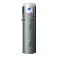
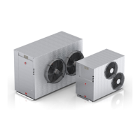
Commercial Air to Water Heat Pump Water Heater
29
MANIFOLD INSTALLATIONS
The commercial heat pump water heater is designed to
be installed with storage tanks on a single manifold or
multiple manifolds if required. The cold water, primary flow
and hot water manifolds must be designed to balance the
flow from each water heater and storage tank. To achieve
this, there are basic installation requirements and prin-
ciples which must be followed:
1. The maximum number of storage tanks in a bank
should be 10, however several banks of storage tanks
can be installed.
2. The hot water line from the manifold must leave from
the opposite end to which the cold water line enters
the manifold.
3. The storage tanks must be of the same model.
4. The cold water line, cold and hot headers and hot wa-
ter line must be sized to meet the requirements of
both AS/NZS 3500.4 and the application.
5. A non-return valve, isolation valve and if required a
pressure limiting valve and expansion control valve,
must be installed on the cold water line to the system.
6. A full flow gate valve or ball valve (not a stop tap, as
used on a single water heater installation) must be
installed on both the cold water branch and hot water
branch of each water heater and storage tank.
7. Non return valves or pressure limiting valves MUST
NOT be installed on the branch lines to the water
heaters or storage tanks.
8. All fittings, valves and branch lines must be matched
sets all the way along the manifold.
9. Sufficient space must be left to enable access, servic-
ing or removal of any water heater or storage tank.
10. The temperature pressure relief valve drain line
from each storage tank can terminate at a common
tundish (funnel) with a visible air break at each drain
discharge point.
AUTHORIZED BALL OR FULL FLOW
OR GATE VALVE
MANIFOLD ARRANGEMENT
Hot Manifold Assembly
 Loading...