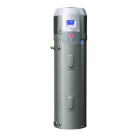
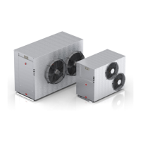
Commercial Air to Water Heat Pump Water Heater
32
CONNECTION SIZES
All plumbing work must be carried out by a qualified per-
son and in accordance with the UL 1995.
WATER INLET AND OUTLET
The pipe work must be cleared of foreign matter before
connection and purged before attempting to operate the
water heater. All olive compression fittings must use brass.
Use thread sealing tape or approved thread sealant on all
screwed fittings.
An isolation valve and non-return valve must be installed
on the cold water line to the water heater system. An ac-
ceptable arrangement is shown in the diagram. Refer also
to “Hot Water Delivery” and to “Mains Water Supply” sec-
tions in this Manual.
Disconnection unions are provided at the cold water inlet
and hot water outlet on the water heater to allow for dis-
connection of the water heater.
PIPE SIZES
To achieve true mains pressure operation, the cold water
line to the storage tanks should be the same size or big-
ger than the hot water line from the storage tanks.
The pipe sizing for hot water supply systems should be
carried out by persons competent to do so, choosing the
most suitable pipe size for each individual application.
Reference to the technical specifications of the water
heater and local regulatory authority requirements must
be made.
Refer to the table on the left for correct primary flow and
return pipe sizing.
RELIEF VALVE
The heat pump is supplied with an integral pressure re-
lief valve located on the inside of the heat pump cabinet
and will discharge into the tray of the heat pump. Refer to
Condensate Drain on next page for drainage instructions.
EXPANSION CONTROL VALVE
Local regulations may make it mandatory to install an
expansion control valve (ECV) in the cold water line to
the water heater system. In other areas, an ECV is not
required unless the saturation index is greater than +0.4
(refer to “Water Supplies” on page 11). However, an ECV
may be needed in a corrosive water area where there are
sufficient quantities of silica dissolved in the water.
The expansion control valve must always be installed after
the non return valve and be the last valve installed prior
to the water heater system (refer to diagram on page 38).
CONNECTIONS - PLUMBING
Model 60k BTU 135k BTU
Heat pump water heater inlet
connection
1¼" NPT 2" NPT
Heat pump water heater outlet
connection
1¼ NPT 2" NPT
Condensate drain connection
13/16"
Ball Valve
 Loading...