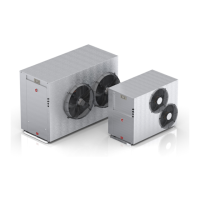
Commercial Air to Water Heat Pump Water Heater
43
CONNECTIONS - ELECTRICAL
D. Input/output View – Displays the actual readings as fol-
lows:
E. Alarm History – will display up to 150 alarm events and
then will overwrite oldest event. Alarms can be cleared
by pressing the ‘Alarm Bell’ key.
F. Service – password: 0022
a. Change display (do not use)
b. Information – software version information
c. Summer/Winter (not applicable to this product)
d. Working Hours:
i. Circ. Pump / reset counter
ii. Compressor 1 / reset counter
iii. Outdoor Fan 1 / reset counter
e. BMS configuration (will time out after 5 minutes if no
buttons pressed)
Address: 1 (if BMS Interface Card Modbus on RS485 is
used, change the address value based on the unique ad-
dress set by the customer’s network. For all other BMS
interface cards, ignore this value).
Protocol: CAREL/Modbus (choose Modbus only for BMS
Interface Card Modbus on RS485. For all other BMS inter-
face cards, choose CAREL).
Speed: 19200 (if BMS Interface Card Modbus on RS485
is used, change the speed value based on the customer’s
network. For all other BMS interface cards, use 19200 as
speed).
f. Service Settings
a. Working Hour Set
b. Prove Adjustment
c. Thermoregulation (for multiple heat pump
installation, change the no. of compressor and
other settings from the table on the next page.)
d. User DEV/Change PW1
For more information, please refer to the service manual
for heat pumps.
Hot Enter Temp: Potable water temperature entering and
leaving the condenser heat exchanger
Hot Leave Temp:
Cold enter Temp: Non-potable/chilled water temperature
entering and leaving the evaporator heat
exchanger
Cold Leave Temp:
Compressor 1 – Compressor temperature and pressure
readings
Low Press:
sat. suction:
Suction:
High Press:
sat. condenser:
out. coil Temp: Evaporator coil temperature
LP1 switch: OK Hi and Lo pressure switches closed or
open circuit
HP1 switch: OK
Flow switch: On/Off Flow switch in non-potable/chilled water
circuit activated
Comp O/Load: On/Off Compressor overload activated
Remote: On/Off Remote control of heat pump activated
Compressor 1: On/Off Compressor status
Rev. valve: On/Off Reversing valve status (NA)
Fan: On/Off Fan status
Circ. Pump: On/Off Primary pump/s status (NB: both non-
potable/chilled and potable water pumps
are activated by same relay)
Outside Temp: Ambient air sensor temperature
Tank Temp: Temperature at near bottom of tank
Building Flow Temp: Temperature being delivered to building
ow
Digital Inputs: Displays the number of inputs and
outputs
Relay Outputs:
 Loading...