13
Tubing
INSTALLATION
Interconnecting Tubing (cont�)
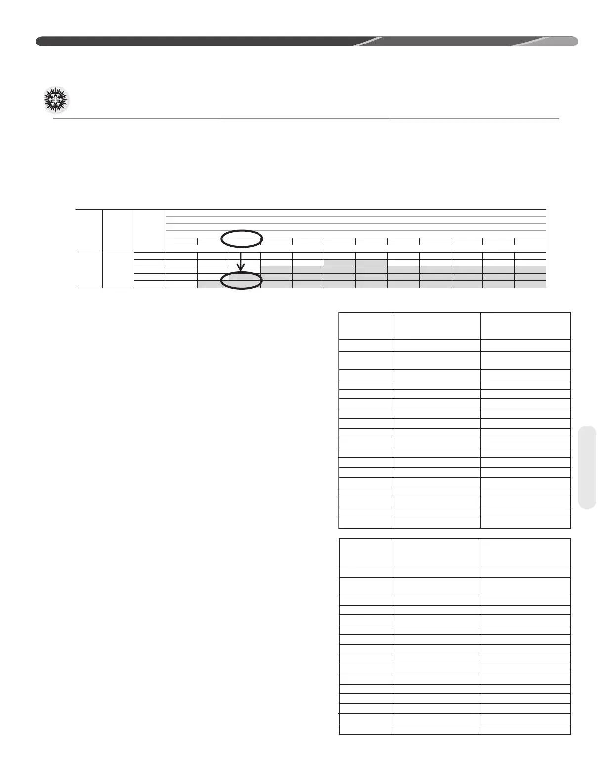
Example: A 3-Ton condensing unit is installed 50’
below the ID unit, requires a 75’ of 1/2” diameter
liquid line, and 4 90° LR elbows�
• Fitting Equivalent Length (ft�) = 4 x �9 = 3�6’
• Total Equivalent Length (ft�) = 75’ + 3�6’ = 78�6’
• Rounded-down value (ft�) = 75’
R-410A
System
Capacity
Model
Liquid Line
Size
Connection
Size (Inch
I.D.) [mm]
Liquid Line
Size (Inch
O.D.) [mm]
Liquid Line Size
Elevation (Above or Below) Indoor Coil
Total
Equivalent
Length - Feet [m]
25 [7.62] 50 [15.24] 75 [22.86] 100 [30.48] 125 [45.72] 150 [45.72] 175 [53.34] 200 [60.96] 225 [68.58] 250 [76.20] 275 [83.82] 300 [91.44]
Maximum
Vertical Separation - Feet [m]
37 3/8" [9.53]
1/4 [6.35] 25 [7.62]
N/R N/R N/R N/R N/R N/R N/R N/R N/R N/R N/R
5/16 [7.94] 25 [7.62] 50 [15.24] 60 [18.29] 45 [13.72] 35 [10.67] 20 [6.1] 5 [1.52]
N/R N/R N/R N/R N/R
3/8 [9.53] 25 [7.62] 50 [15.24] 75 [22.86] 80 [24.38] 80 [24.38] 75 [22.86] 70 [21.34] 65 [19.81] 60 [18.29] 55 [16.76] 50 [15.24] 45 [13.72]
7/16 [11.12] 25 [7.62] 50 [15.24] 75 [22.86] 95 [28.96] 90 [27.43] 90 [27.43] 85 [25.91] 85 [25.91] 85 [25.91] 80 [24.38] 80 [24.38] 80 [24.38]
1/2 [12.71] 25 [7.62] 50 [15.24] 75 [22.86] 95 [28.96] 95 [28.96] 95 [28.96] 95 [28.96] 95 [28.96] 95 [28.96] 90 [27.43] 90 [27.43] 90 [27.43]
This application is acceptable because the 50’
vertical rise is less than the maximum rise of 75’ for
this application� The application is also considered
to have a long line set� Reference the long line set
section of the I&O for detail�
Long Line Set Applications
Long line set applications are dened as ap-
plications that require accessories or alternate
construction methods� The following are special
considerations that need to be addressed when
installing a long line set application:
• Additional refrigerant charge
• Fitting losses and maximum equivalent length
considerations
• Refrigerant migration during the o cycle
• Oil return to the compressor
• Capacity losses
• System oil level adjustment
Table 2 is used to determine if the application is
considered to have a long line set� The region of
the chart that is shaded grey is considered to
be a long line set application.
Oil Level Adjustments for
Long Line Set Applications
Additional oil will need to be added for long line set
applications� (Ref� Table 2)� Below is the equation
for the oil level adjustment and the compressor
name plate oil charge for the dierent od units.
Oil to be Added = [(Charge Adjustment + OD
Unit Name Plate Charge (oz.)) x (0.022) – [(0.10)
x (Compressor Name Plate Oil Charge (oz.))]
Example: An application requires 125ft of line set
with a liquid line diameter of 3/8”, Charge Adjust-
ment = 52�4 oz�, Name Plate Charge = 107 oz�,
Name Plate Oil Charge = 25 oz�, Oil to be Added =
((52�4 oz� +107 oz�) x �022) – (�10 x 25 oz�) = 1�0 oz�
(excerpt fromTable 2, page 16)
RA13
OD Model
Compressor
Name Plate Oil
Charge (oz)
RA1318AJ
RA1318AJ
Alternate
RA1324AJ
RA1330AJ
RA1336AJ
RA1342AJ
RA1348AJ
RA1360AJ
RA1336AC
RA1342AC
RA1348AC
RA1360AC
RA1336AD
RA1342AD
RA1348AD
RA1360AD
RA1348AY
RA1360AY
ZP14KAE-PFV-130
ZP14K6E-PFC-130
ZP20KAE-PFV-130
ZP24K5E-PFV-130
ZP31K6E-PFV-130
ZP34K5E-PFV-130
ZP42K5E-PFV-130
ZP51K5E-PFV-130
ZP31K6E-TF5-130
ZP34K5E-TF5-130
ZP42K5E-TF5-130
ZP51K5E-TF5-130
ZP31K6E-TFD-130
ZP34K5E-TFD-130
ZP42K5E-TFD-130
ZP51K5E-TFD-130
ZP42K5E-TFE-130
ZP51K5E-TFE-130
21
21
21
25
25
42
42
42
25
42
42
42
25
42
42
42
42
42
RA14
OD Model
Compressor
Name Plate Oil
Charge (oz)
RA1418AJ
RA1418AJ
Alternate
RA1424AJ
RA1430AJ
RA1436AJ
RA1442AJ
RA1448AJ
RA1460AJ
RA1436AC
RA1442AC
RA1448AC
RA1460AC
RA1436AD
RA1442AD
RA1448AD
RA1460AD
ZP14KAE-PFV-130 21
21
21
25
25
42
42
42
25
42
42
42
25
42
42
42
ZP14K6E-PFC-130
ZP20KAE-PFV-130
ZP24K5E-PFV-130
ZP29K5E-PFV-130
ZP34K53-PFV-130
ZP39K5E-PFV-130
ZP49K6E-PFV-130
ZP31K6E-TF5-130
ZP34K5E-TF5-130
ZP42K5E-TF5-130
ZP51K5E-TF5-130
ZP31K6E-TFD-130
ZP34K5E-TFD-130
ZP42K5E-TFD-130
ZP51K5E-TFD-130

 Loading...