35
CONDENSATE DRAIN
FOR HORIZONTAL
INSTALLATION
Refer to Figure 33 for Steps 1-4.
This unit is shipped factory ready for
downflow installation. The
condensate trap assembly and drain
hoses require conversion for
horizontal installation. Remove the
existing condensate trap with the unit
in the upright position.
1. Remove the burner compartment
door from the unit.
2. Remove the two screws from the
right side of the furnace jacket
which support the trap mounting
bracket. Remove the two
plastic plugs on either side of the
trap outlet hole and discard.
3. Remove the black molded 90°
hose ➂ from the top of the
existing trap ➀ and furnace
collector box. Cut 1.0 inch from
the long end of the hose. NOTE:
Exception – do not shorten the
90° hose on the 07B furnace!
The 07B has a longer distance
between the collector box and
horizontal drain trap.
4. Remove the double-elbow black
molded hose ➀ from the exhaust
transition ➀. Discard this hose
and the downflow trap.
NOTE: The following steps should
take place with the furnace in the
horizontal position.
Refer to Figure 34 for Steps 6-11.
5. Locate the parts bag in the
burner compartment. Install two
plastic plugs ➅ in the side of the
jacket from bottom side up.
6. Fill the trap assembly ➆ with a
cup of water.
7. Attach the gasket ➇ onto the trap
assembly so that the gasket
holes on the gasket line up with
the holes on the trap assembly.
8. Insert the trap assembly with
gasket up through the existing
hole in the jacket and secure
from inside the jacket. Use two
screws provided. Screw down
into the two “ears” molded into
either side of the trap. Snug the
trap assembly against the
furnace jacket compressing the
gasket slightly to eliminate any
air leaks. Do not
overtighten!
9. Attach the black molded rubber
90° elbow ➈ to the straight spout
on the trap top using a white
nylon clamp ➉. Attach the other
end of the rubber elbow to the
spout ➋ located on the exhaust
transition ➄ using a white nylon
clamp.
10. Attach the 90° end of the molded
hose to the collector box.
Clamp the hose tight with white
nylon clamp. Then attach the
long end of the molded hose to
the 45° elbow molded into the top
of the trap assembly. Clamp the
hose tight with white nylon clamp.
IMPORTANT: Tighten all clamp
connections with a pair of pliers
and check for leaks after
conversion is complete.
11. IMPORTANT: There are two
options when choosing a height for
the condensate riser:
CONDENSATE OVERFLOW: With
a 1
3
⁄4 inch riser installed above the
tee, a blocked drain will result in
overflow from the riser.
FURNACE SHUTDOWN: To
cause the furnace to shut down
when a blocked drain is present,
install a riser which is a minimum
of 5
1
⁄2”. If the furnace is installed in
an attic, crawlspace or other area
where freezing temperatures may
occur, the furnace drain can freeze
while shut off for long periods of
time. Provisions must be made to
prevent freezing of condensate
(see Figure 3).
Use a solvent cement that is
compatible with PVC material.
NOTE: See location requirements and
combustion section for additional
recommendations.
FILLING THE TRAP
FILL THE TRAP ASSEMBLY WITH
WATER BEFORE OPERATING THE
FURNACE. Do this by removing the
drain hose from the trap or from the
connection to the secondary coil.
Pour about a cup of water into the
vent trap. Any excess water flows into
the house drain when the trap is full.
NOTE: Fill the trap assembly with
water every heating season.
B
C
A
D
E
F
G
H
I
J
K
E
L
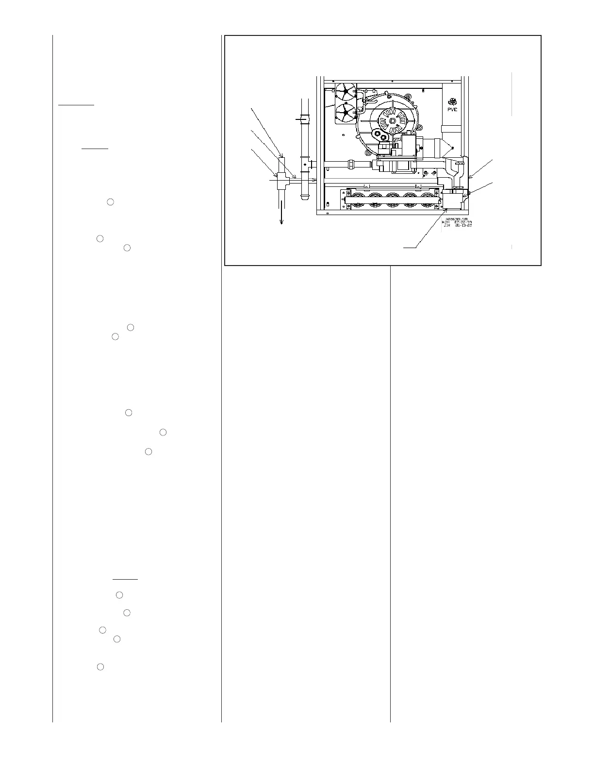
FIGURE 32
DOWNFLOW OPPOSITE SIDE CONDENSATE TRAP CONNECTION
UNION
DRIP LEG
BURNERS
MANIFOLD
CONDENSATE TRAP
DRAIN
VENT
DRAIN
EXTENSION
TEE
TO FLOOR
DRAIN OR
CONDENSATE
PUMP
ROTATE TRAP
180° AND
INSTALL RIGID
PIPE FROM
ELBOW TO
OPPOSITE
SIDE OF
JACKET AS
SHOWN.
EXISTING
DRAIN HOLE.
PLUG WITH
1 5/8” PLUG
SUPPLIED IN
KIT.
ALTERNATE
DRAIN HOLE
LOCATED
HERE ON
JACKET.
(REMOVE
PLASTIC PLUG
AND REPLACE
WITH
GROMMET).
 Loading...