37
GAS SUPPLY AND PIPING
GAS SUPPLY
THIS FURNACE IS EQUIPPED AT
THE FACTORY FOR USE ON
NATURAL GAS ONLY. CONVERSION
TO LP GAS REQUIRES A SPECIAL
KIT IS AVAILABLE AT THE
DISTRIBUTOR. FAILURE TO USE
THE PROPER CONVERSION KIT
CAN CAUSE FIRE, CARBON
MONOXIDE POISONING,
EXPLOSION, PROPERTY DAMAGE,
PERSONAL INJURY OR DEATH. See
the conversion kit index supplied
with the furnace. This index
identifies the proper LP Gas
Conversion Kit required for each
particular furnace.
IMPORTANT: Any additions, changes
or conversions required for the furnace
to satisfactorily meet the application
should be made by a qualified installer,
service agency or the gas supplier,
using factory-specified or approved
parts.
IMPORTANT: Connect this furnace
only to gas supplied by a commercial
utility.
IMPORTANT: U.L. or CSA recognized
fuel gas and CO detector(s) are
recommended in all applications, and
their installation should be in
accordance with the manufacturer’s
recommendations and/or local laws,
rules, regulations or customs.
GAS PIPING
Install the gas piping according to all
local codes and regulations of the utility
company.
If possible, run a separate gas supply
line directly from the meter to the
furnace. Consult the local gas company
for the location of the manual main
shut-off valve. The gas line and
manual gas stop must be adequate
in size to prevent undue pressure
drop and never smaller than the pipe
size to the gas valve on the furnace.
Refer to Table 6 for the recommended
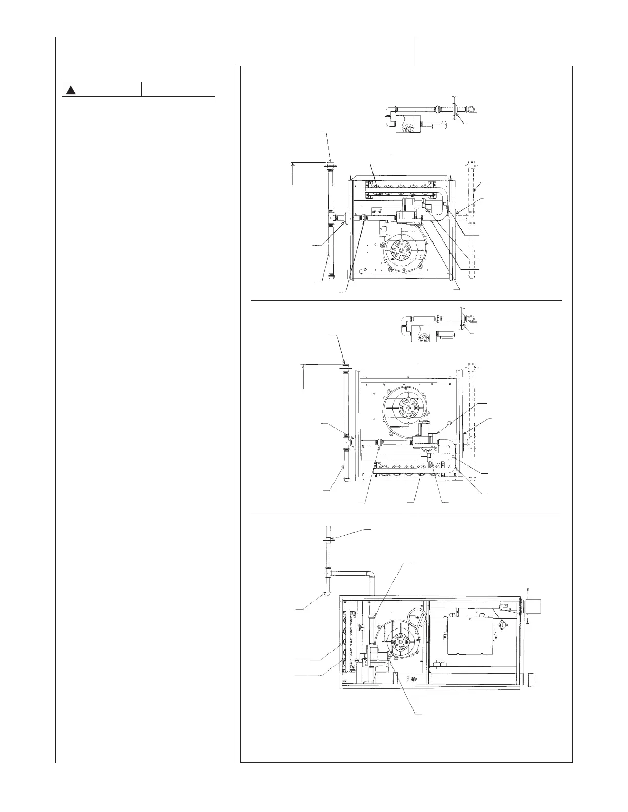
gas pipe size. See Figure 35 for typical
gas pipe connections.
Install a ground joint union within 3 ft.
of the cabinet to easily remove the
gas valve assembly. Install a manual
gas stop valve in the gas line outside
the furnace casing. The manual gas
stop should be readily accessible to
turn the gas supply on or off. Install a
drip leg in the gas supply line as close
to the furnace as possible. Always
!
WARNING
FIGURE 35
GAS PIPING INSTALLATION
GROMMET
TOP VIEW OF GAS LINE AND VALVE
IN OPT. POSITION
NOTE: WHEN GAS LINE
IS IN OPT. POSITION,
SWAP LOCATION OF
GROMMET AND PLUG.
OPT. GAS LINE
POSITION
PLUG
(IN NORMAL
POSITION)
MANIFOLD
PRESSURE
TAP
IGNITOR
MANIFOLD
GAS VALVE
UNION
DRIP LEG
GROMMET
(IN NORMAL
POSITION)
4 TO 5 FEET
ABOVE
FLOOR REQ’D
BY SOME
UTILITIES.
MANUAL
GAS
STOP
BURNERS
GROMMET
TOP VIEW OF GAS LINE AND VALVE
IN OPT. POSITION
MANUAL
GAS
STOP
4 TO 5 FEET ABOVE
FLOOR REQ’D BY
SOME UTILITIES.
GROMMET
(IN NORMAL
POSITION)
DRIP LEG
UNION
GAS VALVE
BURNERS
MANIFOLD
IGNITOR
MANIFOLD
PRESSURE
TAP
PLUG
(IN NORMAL
POSITION)
NOTE: WHEN GAS
LINE IS IN OPT.
POSITION, SWAP
LOCATION OF
GROMMET AND
PLUG.
DOWNFLOW
I328
UPFLOW
MANUAL GAS STOP
UNION
DRIP LEG
BURNERS
MANIFOLD
GAS VALVE
I524
IMPORTANT: DO NOT RUN A FLEXIBLE GAS CONNECTOR INSIDE THE
UNIT. Extend the 1/2" black pipe from the gas valve to the outside of the
cabinet.
HORIZONTAL
 Loading...