EasyManua.ls Logo

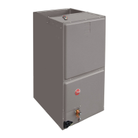
Rheem RH1V3617STANJA User Manual

Rheem RH1V3617STANJA
56 pages
To Next Page IconTo Next Page
Page #1 background imageLoading...
Page #1 background image
INSTALLATION INSTRUCTIONS
AIR HANDLERS
FEATURING INDUSTRY STANDARD R-410A REFRIGERANT:
(-)H1V Premium Efficiency Single Stage with Aluminum Coil
(-)H2V Premium Efficiency Two Stage Comfort Control
2
System™
(-)H2V with Aluminum Coil
refrigerant
WARNING
WARNING
!
These instructions are intended as an aid to qualified licensed
service personnel for proper installation, adjustment and
operation of this unit. Read these instructions thoroughly before
attempting installation or operation. Failure to follow these
instructions may result in improper installation, adjustment,
service or maintenance possibly resulting in fire, electrical
shock, property damage, personal injury or death.
ISO 9001:2008
92-20521-65-02
SUPERSEDES 92-20521-65-01

Table of Contents

Question and Answer IconNeed help?

Do you have a question about the Rheem RH1V3617STANJA and is the answer not in the manual?

Rheem RH1V3617STANJA Specifications

General IconGeneral
BrandRheem
ModelRH1V3617STANJA
CategoryAir Handlers
LanguageEnglish

Summary

Safety Information

Electrical Wiring

Covers all aspects of electrical wiring for the air handler unit installation.

Control Wiring

Guidelines for low voltage control wiring and thermostat connections.

Typical Thermostat Wiring Diagrams (-)H1V

Illustrates common thermostat wiring configurations for the (-)H1V model.

Grounding

Essential safety instructions for proper unit grounding.

Conventional 24VAC Thermostat Control Wiring (-)H2V

Wiring diagrams for conventional 24VAC thermostat control for (-)H2V models.

Electric Heat Electrical Data (-)H1V

Electrical data for electric heat kits compatible with (-)H1V models.

Electric Heat Electrical Data (-)H2V

Electrical data for electric heat kits compatible with (-)H2V models.

ECM Motor Interface Control Board (-)H1V

Details on the ECM motor interface control board for (-)H1V air handlers.

Cooling and Heat Pump Heating Mode Airflow Settings (-)H1V

Airflow settings for cooling and heat pump modes on (-)H1V models.

Cooling/Heating Airflow Adjustments (-)H1V

Adjusting airflow settings for cooling and heating on (-)H1V models.

Air Handler Equipped with the Comfort Control² System™™ Interface Board (-)H2V

Details on the Comfort Control² system interface board for (-)H2V air handlers.

Ductwork

Guidelines and requirements for proper ductwork installation.

Refrigerant Connections

Procedures for making refrigerant line connections to the coil.

Sequence of Operation

Describes how the unit operates in different modes like cooling and heating.

Pre-Start Checklist

A comprehensive checklist before starting the unit.

Maintenance

Procedures for maintaining the air handler for optimal performance.

Safety Information Warnings

Duct Leak Hazards

Highlights risks associated with duct leaks, including pollutant migration.

Installation Without Indoor Coil Warning

Safety warning regarding installation without an indoor coil.

ECM Control Module Replacement Warning

Safety warning for replacing the ECM control module.

Electrical Wiring Safety Warning

Safety warning about disconnecting power before electrical work.

Grounding Safety Warning

Safety warning emphasizing the necessity of proper grounding.

Maintenance Access Warning

Safety warning related to maintenance access and electrical hazards.

Additional Safety Information

Plenum and Ductwork Construction Warning

Safety warning about plenum construction and material requirements.

Ductwork Connection Warning

Safety warning against connecting return ductwork to other heat-producing devices.

Service Personnel Warning

Warning that installation and service should be done by trained personnel.

Combustible Floor Base Warning

Safety warning about using a combustible floor base for downflow units.

Installation Cautions and Notices

Grounding

Safety Warning

Electrical Wiring

Power Wiring

Instructions for connecting the main power supply to the air handler.

Control Wiring

Typical Thermostat Wiring Diagrams (-)H1V

Typical Thermostat Wiring Diagrams (-)H2V

Typical Thermostat Wiring Diagrams (-)H2V - continued

Conventional 24VAC Thermostat Control Wiring (-)H2V

Electric Heat Electrical Data (-)H1V

Electric Heat Electrical Data (-)H1V - continued

Electric Heat Electrical Data (-)H2V

Air Handler Equipped with ECM Motor Interface Control Board (-)H1V

ECM Motor Interface Control and Settings

Configuration and settings for the ECM motor interface control board.

Cooling and Heat Pump Heating Mode Airflow Settings (-)H1V

Cooling/Heating Airflow Adjustments (-)H1V

Electric Heat Airflow Settings/Adjustments (-)H1V

Air Handler Equipped with the Comfort Control² System™™ Interface Board (-)H2V

Comfort Control² System™™ Control Wiring

Wiring requirements for the Comfort Control² system.

Cooling Airflow Settings (By Tonnage) (-)H2V

Cooling Airflow Settings

Airflow Adjustment (-)H2V (Trim)

Electric Heat Airflow

Ductwork

Refrigerant Connections

Sequence of Operation

Pre-Start Checklist

Maintenance

Blower Assembly Removal and Replacement

Blower Assembly Removal Warning

Safety warning for blower assembly removal and electrical shock risk.

ECM Motor Components Warning

Related product manuals