Do you have a question about the Rheem RH1V4821STANJA and is the answer not in the manual?
Warnings about duct leaks drawing pollutants into living spaces, causing property damage or injury.
Warning about placing units over combustible materials without proper base to prevent fire.
Caution regarding power disconnection before replacing ECM module to prevent injury or damage.
Warning about disconnecting all power before electrical work to prevent severe injury or death.
Importance of permanent grounding to prevent electrical shock, personal injury or death.
Warning about energized line side of circuit breakers during maintenance causing shock.
Safety precautions for de-energizing and locking out power during blower assembly removal.
Information on Proposition 65, fiberglass insulation, and potential chemical exposures.
Requirements for supply air plenum and ductwork construction near the unit to prevent fire.
Warning against connecting return ductwork to other heat-producing devices to prevent fire.
Recommends trained personnel for installation, service, and maintenance.
Requirement for a combustible floor base for downflow applications on combustible flooring.
Caution about reversing the 5-pin ECM motor connector potentially causing module failure.
Discusses power supply, disconnects, wire types, and connection points for power wiring.
Electrical specifications for H1V electric heater kits.
Continues electrical data for H1V electric heater kits.
Electrical specifications for H2V electric heater kits.
Explains the function of DIP switches on the ECM control board.
Details passive and active dehumidification modes and airflow adjustments.
Wiring requirements for Comfort Control² and board features.
Explains On Demand Dehumidification (ODD) operation and airflow reduction for humidity control.
A checklist of critical items to verify before initial system startup.
Detailed steps for replacing the ECM control module on the blower motor.
| Model | RH1V4821STANJA |
|---|---|
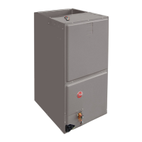
| Type | Air Handler |
| Refrigerant | R-410A |
| Voltage | 208/230V |
| Phase | 1 |
| Motor Type | ECM |
| Width | 21 inches |
| Depth | 21 in |