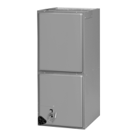
Do you have a question about the Rheem RH1P3617STANJA and is the answer not in the manual?
Critical warnings regarding electrical hazards, grounding, and service disconnects.
Warnings about installation risks, ductwork integrity, and proper unit configuration.
Information on potential health risks from materials and operation, and environmental factors.
Importance of filters and ductwork integrity for safe operation and preventing hazards.
Mandatory grounding procedures to ensure electrical safety and prevent shock.
Electrical data for (-)H1P models with electric heater kits, detailing KW, voltage, amps, and circuit protection.
Further electrical data for (-)H1P models with electric heater kits.
Electrical data for (-)H1T models with electric heater kits, detailing KW, voltage, amps, and circuit protection.
Further electrical data for (-)H1T models with electric heater kits.
Airflow performance data for (-)H1P models at 240V, showing CFM, RPM, and Watts.
Continued airflow data for (-)H1P PSC motor models at 240V.
Airflow performance data for (-)H1P PSC motor models at 115/208/480V.
Continued airflow data for (-)H1P PSC motor models at 115/208/480V.
Airflow data for (-)H1T ECM motor models at 115/208/240/480V.
Final airflow data for (-)H1T ECM motor models at 115/208/240/480V.
Checklist of essential items to verify before starting the unit for operation.
Procedures for performing an operational check-out after installation.
Method to estimate airflow by measuring external static pressure against the unit.
Method to estimate airflow using temperature rise across electric heat elements.
Procedure for checking refrigerant charge after confirming correct airflow.
Information on available electric heater kits, their ratings, and installation.
Electrical wiring diagram for (-)H1P air handler operating on 115V.
Electrical wiring diagram for (-)H1P air handler operating on 208/240V.
| Model | RH1P3617STANJA |
|---|---|
| Type | Air Handler |
| Cooling Capacity | 3 Tons |
| Airflow | 1200 CFM |
| Refrigerant | R-410A |
| Phase | 1 |
| Frequency | 60 Hz |
| Motor Type | PSC |
| Max. External Static Pressure | 0.5 in. w.c. |
| Cabinet | Galvanized Steel |
| Depth | 21 inches |
| Voltage | 208/230V |
| Filter Type | 1" Disposable |
| Width | 21 inches |


 Loading...