EasyManua.ls Logo

Rheem RH1T2417STANAA User Manual

Rheem RH1T2417STANAA
56 pages
To Next Page IconTo Next Page
Page #1 background imageLoading...
Page #1 background image
WARNING
sWARNING
!
These instructions are intended as an aid to qualified licensed
service personnel for proper installation, adjustment and
operation of this unit. Read these instructions thoroughly before
attempting installation or operation. Failure to follow these
instructions may result in improper installation, adjustment,
service or maintenance possibly resulting in fire, electrical
shock, property damage, personal injury or death.
AIR HANDLERS
FEATURING INDUSTRY STANDARD R-410A REFRIGERANT:
(-)H1P Standard Efficiency with Aluminum Coil
(-)H1T High Efficiency with Aluminum Coil
INSTALLATION INSTRUCTIONS
92-20521-110-00
(BASED ON 92-20521-66-09)
Question and Answer IconNeed help?

Do you have a question about the Rheem RH1T2417STANAA and is the answer not in the manual?

Rheem RH1T2417STANAA Specifications

General IconGeneral
BrandRheem
ModelRH1T2417STANAA
CategoryAir Handlers
LanguageEnglish

Summary

1.0 SAFETY INFORMATION

2.7 IMPORTANCE OF QUALITY INSTALLATION

3.0 INSTALLATION

3.1 TOOLS & REFRIGERANT

Lists required tools and information about R-410A refrigerant for installation.

3.2 APPLICATIONS AND ORIENTATION

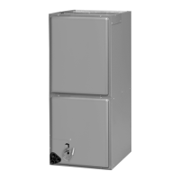
Details how to install the unit in different configurations like upflow, downflow, and horizontal.

3.9 REFRIGERANT LINE CONNECTIONS & CHARGING

Procedures for preparing, brazing, leak testing, and charging refrigerant lines.

3.13 ELECTRICAL WIRING

General guidelines for field wiring, including configuration for different voltages and grounding.

3.13.6.1 ELECTRICAL DATA – WITH ELECTRIC HEAT: (-)H1P

Electrical data for (-)H1P models with electric heater kits, including kW and amperage.

3.13.6.2 ELECTRICAL DATA – WITH ELECTRIC HEAT: (-)H1T

Electrical data for (-)H1T models with electric heater kits, including kW and amperage.

3.14 AIRFLOW

Information on selecting airflow based on performance data tables and operating limits.

3.14.2 SELECTING INDOOR BLOWER MOTOR SPEED

Instructions for selecting the correct blower motor speed tap based on external static pressure.

4.0 START-UP

4.1 PRE-START CHECKLIST

A checklist of essential items to verify before starting the system.

4.2 SYSTEM START-UP AND OPERATIONAL CHECK-OUT

Procedures for performing an operational check-out after installation.

4.6 CHECKING INDOOR AIR-FLOW

Methods for checking and estimating indoor airflow.

4.7 CHECKING REFRIGERANT CHARGE

Procedures for checking refrigerant charge after confirming correct airflow.

6.0 ACCESSORIES & KITS

6.1 ELECTRIC RESISTANCE HEATER KITS

Details on available electric heater kits, their specifications, and installation notes.

7.0 MAINTENANCE

8.0 DIAGNOSTICS

9.0 WIRING DIAGRAMS

9.1 WIRING DIAGRAM (-)H1P – 115V

Electrical wiring diagram for (-)H1P model operating on 115V.

9.2 WIRING DIAGRAM (-)H1P – 208/240V

Electrical wiring diagram for (-)H1P model operating on 208/240V.

9.3 WIRING DIAGRAM (-)H1P – 480V

Electrical wiring diagram for (-)H1P model operating on 480V.

9.4 WIRING DIAGRAM (-)H1T – 115V

Electrical wiring diagram for (-)H1T model operating on 115V.

9.5 WIRING DIAGRAM (-)H1T – 208/240V

Electrical wiring diagram for (-)H1T model operating on 208/240V.

9.6 WIRING DIAGRAM (-)H1T – 480V

Electrical wiring diagram for (-)H1T model operating on 480V.

Related product manuals