Air
Unit Features & Benefits
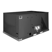
RKNL-B Series
5
Inside the control box ( ), each elec-
trical component is clearly identified
with a label that matches the compo-
nent to the wire diagram for ease of
trouble shooting. All wiring is num-
bered on each end of the termination
and color-coded to match the wiring
diagram. The integrated furnace con-
trol, used to control furnace operation,
incorporates a flashing LED trouble -
shooting device. Flash codes are
clearly outlined on the unit wiring dia-
gram. The control transformer has a
low voltage circuit breaker that trips if a
low voltage electrical short occurs.
There is a blower contactor and com-
pressor contactor for each compressor.
For added convenience in the field, a factory-installed conve-
nience outlet and disconnect ( ) are available. Low and High
voltage can enter either from the side or through the base.
Low-voltage connections are made
through the low-voltage terminal strip.
For ease of access, the U.L.-required
low voltage barrier can be temporarily
removed for low-voltage termination
and then reinstalled. The high-voltage
connection is terminated at the number
1 compressor contactor. The
suggested mounting for the field-
installed disconnect is on the exterior
side of the electrical control box.
To the right of the electrical and filter
compartment are the externally
mounted gauge ports, which are per-
manently identified by embossed
wording that clearly identifies the com-
pressor circuit, high pressure connec-
tion and low pressure connection ( ).
With the gauge ports mounted exter-
nally, an accurate diagnostic of system
operation can be performed quickly and easily. Brass caps on
the shraeder fitting assure that the gauge parts are leak proof.
The blower compartment is to the right of the gauge ports and
can be accessed by 1/4 turn fastener. To allow easy maintenance
of the blower assembly, the entire assembly easily slides out by
removing two 3/8" screws from the blower retention bracket. The
adjustable motor pulley ( ) can easily be adjusted by loosening
the bolts on either side of the motor mount. Removing the bolts
allows for easy removal of the blower pulley by pushing the
blower assembly up to loosen the belt. Once the belt is removed,
the motor sheave can be adjusted to the desired number of
turns, ranging from 0 to 6 turns open. Where the demands for
the job require high static, Rheem has high-static drives available
that deliver nominal airflow up to 2" of static. By referring to the
airflow performance tables listed in the installation instructions,
proper static pressure and CFM requirements can be dialed in.
The scroll housing ( ) and blower scroll provide quiet and effi-
cient airflow. The blower sheave is secured by an “H” bushing
which firmly
secures the pulley
to the blower
shaft for years of
trouble-free oper-
ation. The “H”
bushing allows
for easy removal
of the blower
pulley from the
shaft, as opposed
to the use of a set
screw, which can
score the shaft,
creating burrs that
make blower-
pulley removal difficult.
15
14
13
12
11
10
7
13
11
12
14
15
 Loading...