Do you have a question about the Rheem RRRL and is the answer not in the manual?
California Proposition 65 warning regarding fiberglass insulation and exhaust gases.
Manufacturer's warranty disclaimer for unauthorized components or accessories.
Warning against indoor installation due to performance and CO poisoning risks.
Warning to disconnect power before maintenance to prevent electrical shock.
Units are designed for outdoor installation only; indoor installation is unsafe.
Warning against direct installation on combustible structures.
Warning against connecting return ductwork to other heat-producing devices.
Warning to prevent combustion products from entering return ductwork.
Warning against using open flame to check for gas leaks.
Warning about proper conversion kits for LP gas.
Warning to disconnect power before wiring.
Warning against manual lighting with open flame.
Warning that failure to follow instructions can cause fire or explosion.
Warning about high voltage from spark ignitor and ignition lead.
Emergency procedure for overheating or gas supply failure.
Warning about the overtemperature control and replacement parts.
Warning about toxic fumes from exhaust transition/heat exchanger leaks.
Warning to disconnect power before maintenance.
Warning to label wires before disconnection.
Warning about consequences of wiring errors.
Warning to disconnect power before changing blower speeds.
Warning to disconnect all power before servicing contactor.
Caution regarding R-410A systems and R-22 equipment.
California Proposition 65 warning about chemicals in products.
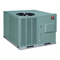
Introduces the unit and installation precautions for satisfaction.
Instructions for inspecting the unit upon receipt and filing claims.
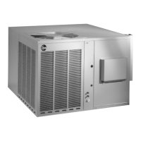
General specifications for the combination gas heating/electric cooling unit.
Lists the major components of the unit.
Details on R-410A refrigerant specifications and properties.
Quick reference guide for R-410A refrigerant handling and properties.
Details on the evaporator coil and TXV compatibility with R-410A.
Lists required tools for R-410A model installation and servicing.
Description of the Comfort Alert™ diagnostics module and its LEDs.
Lists specific Comfort Alert™ flash codes and their meanings.
Information on using thermostats with active compressor protection.
Explains system pressure trip causes and thermostat reaction.
Explains short cycling causes and thermostat reaction.
Explains locked rotor causes and thermostat reaction.
Explains open start circuit causes and thermostat reaction.
Explains open run circuit causes and thermostat reaction.
Procedure for resetting the thermostat after a hard lockout.
Provides unit dimensions and required clearances for installation.
Key points to consider before starting installation.
Guidance on selecting installation locations to avoid corrosion.
Instructions and considerations for outdoor installation.
Instructions for attaching exhaust and combustion air inlet hoods.
Procedures for converting cover panels between configurations.
Minimum clearances required for installation.
Considerations for rooftop installation.
Guidelines for fabricating and sizing ductwork.
Diagram showing exception to non-combustible flooring requirement.
Diagram for flat rooftop installation.
Diagram for pitched rooftop installation.
Diagram for pitched rooftop installation with downflow ductwork.
Guidelines for return air ductwork installation and safety.
Installer must install field-supplied filters in the return air duct.
Diagram showing lifting details for unit installation.
Diagram showing roofcurb installation detail.
Diagram showing roofcurb installation detail with tie-down screws.
Diagram showing ductwork cover installation detail.
Diagram showing residential rooftop ductwork installation detail.
Instructions for connecting the unit to the gas supply.
Approved method for checking gas leaks.
Procedure for converting the unit to LP gas.
Instructions for converting units with NOx inserts to LP gas.
Procedures for adjusting furnace gas input and pressure.
Information on the condensate drain system and trap requirements.
Instructions for connecting the unit's power supply.
Wiring must comply with the National Electrical Code and local codes.
Voltage and phase balance requirements for proper operation.
Guidance on selecting wire size based on circuit ampacity and length.
Warning regarding the use of aluminum wire with unit contactor.
Instructions and diagram for wiring unit hook-up.
Notes on internal wiring, including single pole contactors and transformer voltage.
Requirements for thermostat compatibility and low voltage wiring.
Wiring hook-up diagram for internal components.
Step-by-step description of the normal furnace operating sequence.
Troubleshooting guide based on control board LED flash codes.
Instructions for starting the furnace.
Steps to properly shut down the furnace.
Information on burner adjustment and accessibility.
Description and function of the manual reset overtemperature control.
Function of the pressure switch for exhaust/blower sensing.
Description of the supply air high temperature limit control.
Tips for the customer to improve system operation and efficiency.
Recommended procedures for furnace section annual inspection and cleaning.
Recommendations for inspecting and cleaning the cooling section.
Detailed steps for cleaning the evaporator coil.
Steps for cleaning condenser coil, drain pan, and blower.
Information on motor lubrication and maintenance recommendations.
Explains the ECM motor interface board and its settings.
Explains ECM motor features like soft start/stop and constant airflow.
Emphasizes using exact replacement motors for ECM units.
How the ECM motor is controlled by the thermostat in different modes.
Instructions for adjusting cooling airflow using switches 3 & 4.
Explanation of cooling delay profiles for efficiency and comfort.
Instructions for adjusting heating airflow using switches 5 & 6.
Explanation of the "On Demand Dehumidification" (ODD) feature.
Using switches 9 & 10 to adjust cooling airflow for dehumidification.
General data for RRNL models, nominal sizes 2-5 tons.
General data for RRPL models, nominal sizes 2-5 tons.
General data for RRRL models, nominal sizes 2-5 tons.
Electrical data for RRNL series units.
Electrical data for RRPL series units.
Electrical data for RRRL series units.
Indoor airflow performance data for 208V units.
Indoor airflow performance data for 230V units.
Indoor airflow performance data for RRRL 208/230V units.
Wiring diagram schematic.
Wiring diagram for the unit's electrical components.
Electrical wiring diagram for various unit configurations.
Electrical wiring diagram for integrated furnace control.
Electrical wiring diagram for ECM blower motor models.
Electrical wiring diagram for 5-ton gas electric 2/3 wire control.
Electrical wiring diagram for integrated furnace control.
Electrical wiring diagram for 2, 3, 4-ton models.
Electrical wiring diagram for 3-ton models.
System charge chart for 2-ton cooling.
System charge chart for 2 1/2 ton cooling.
System charge chart for 3 ton cooling.
System charge chart for 3 1/2 ton cooling.
System charge chart for 4 ton cooling.
System charge chart for 5 ton cooling (RNL).
System charge chart for 5 ton cooling (RPL 1st stage).
System charge chart for 5 ton cooling (RPL 2nd stage).
System charge chart for RRRL 2 ton cooling (1st stage).
System charge chart for RRRL 2 ton cooling (2nd stage).
System charge chart for RRRL 3 ton cooling (1st stage).
System charge chart for RRRL 3 ton cooling (2nd stage).
System charge chart for RRRL 4 ton cooling (1st stage).
System charge chart for RRRL 4 ton cooling (2nd stage).
System charge chart for RRRL 5 ton cooling (1st stage).
System charge chart for RRRL 5 ton cooling (2nd stage).
Troubleshooting guide for common unit issues and their remedies.
Furnace troubleshooting guide flowchart.
Troubleshooting information for single-phase Comfort Alert™ system.
Troubleshooting information for three-phase Comfort Alert™ system.
| Brand | Rheem |
|---|---|
| Model | RRRL |
| Category | Air Conditioner |
| Language | English |