32
Horizontal Vent and Combustion, Air-Inlet Alternate
Vent Riser Terminal Installation
INSTALLATION INSTRUCTIONS
Read these instructions thoroughly and make sure
you understand all steps and procedures before
proceeding with the installation.
Determine the locations for the vent and combustion
air-inlet terminals then make two (2) holes through
the exterior wall to accommodate the vent and
combustion air-inlet pipes.
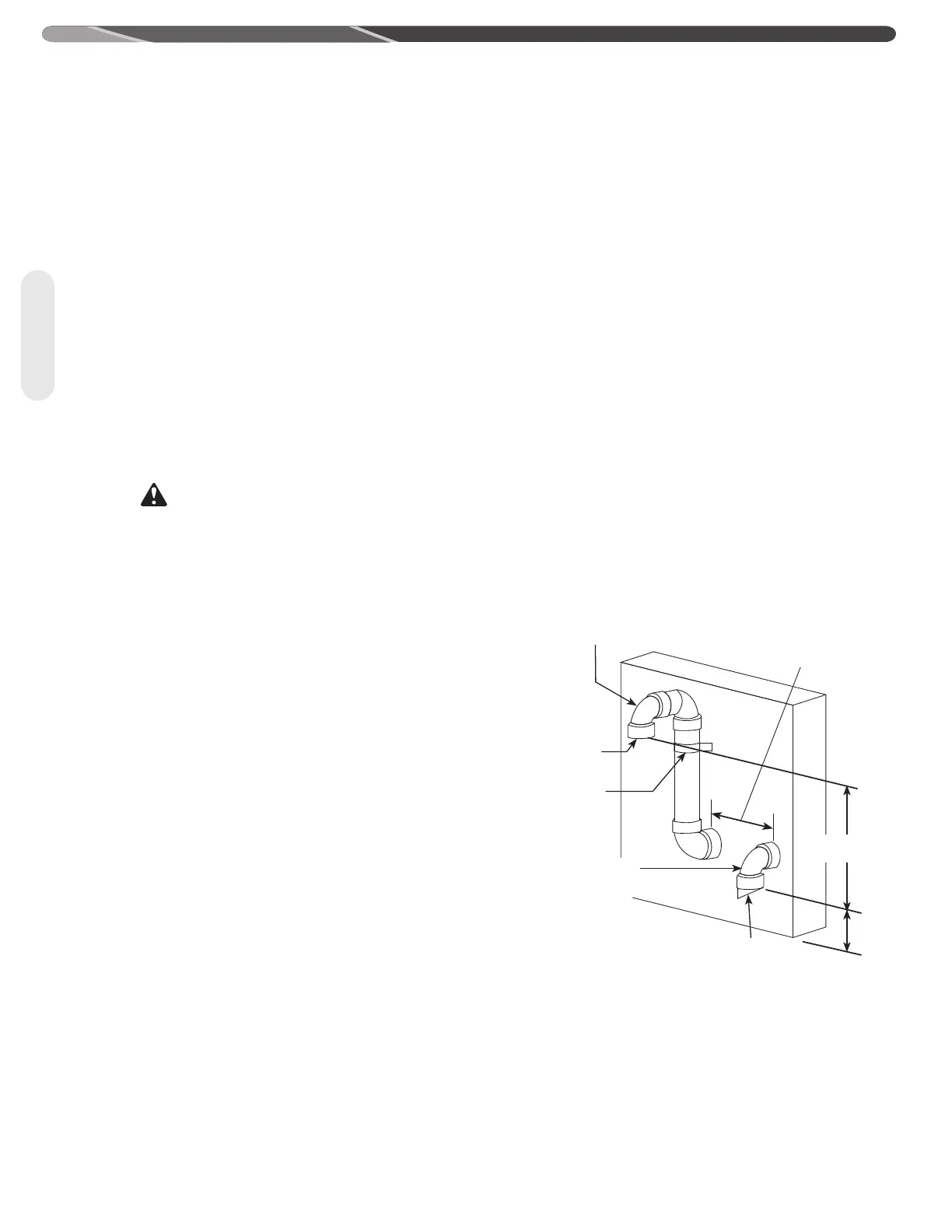
The horizontal distance between the vent and
combustion air-inlet terminal centerlines must be
from 12 in. (30.5 cm) minimum to 36in. (91.4 cm)
maximum.
The vertical distance between the outlet of the vent
terminal to the outlet of the combustion air-inlet
terminal must be from 0 in. (0 cm) minimum to 36 in.
(91.4 cm) maximum.
WARNING:
The vent terminal must always be installed at the same
height or vertically higher than the combustion air-inlet
terminal.
Maintain a minimum distance from the outlets of the
vent and combustion air-inlet terminals of not less
than 12 in. (30.5 cm) above grade or average snowfall
whichever is greater.
IMPORTANT:
The vent terminal must always be installed at the same
height or vertically higher than the combustion air-inlet
terminal.
Insert lengths of vent and combustion air-inlet pipes
through the wall as shown.
Allow sufficient length of pipe to extend beyond the
exterior wall of the building for attachment of the
vent riser assemblies as shown.
Place the supplied 1/2 in. (1.3 cm) mesh metal screen
inside exhaust vent terminal fitting (optional).
NOTICE:
For cold climates the screen may be removed.
Connect the vent riser assemblies to the vent and
combustion air-inlet pipes which are extending out of
the building.
Ensure that the back of the 90° elbows are flush
with the outside wall surface and that the vent and
combustion air-inlet terminations of the vent risers
are parallel with the outside wall.
IMPORTANT:
Remember to include the additional 90° elbows and vertical
height of vent and combustion air-inlet pipes of the vent
riser when calculating the maximum equivalent vent
and combustion air-inlet system lengths. The maximum
equivalent vent and combustion air-inlet system lengths
must be as specified by the tables shown in the Use and
Care Manual.
The vent and combustion air-inlet terminations are
not included in the equivalency calculations.
Complete the installation of the remainder of the vent
system and attach it to the vent connector fitting on
the water heater's blower assembly.
Horizontal sections of the vent system must slope
downward toward the water heater a minimum of 1/8
in. per foot (10 mm per m).
DO NOT use unequal diameters of pipe and fittings
for the vent and combustion air-inlet systems except
as defined previously.
NOTICE: The difference between the vent and
combustion air-inlet system equivalent lengths must
be no greater than 5 ft. (1.5 m).
Complete the installation of the remainder of the
combustion air-inlet system and attach it to the
combustion air-inlet connector fitting on the water
heater's combustion air-inlet tube assembly.
Support vertical and horizontal lengths of the vent
and combustion air-inlet systems as previously
mentioned.
90° Vent
Terminal Elbow
90° Combustion
Air-Inlet Terminal Elbow
*Wind Vane
Mesh
Screen
Inside
(Optional)
Securing
Strap
(Optional)
0 in. (0 cm) min.
36 in. (91.4 cm) max.
12 in. (30.5 cm) min.
36 in. (91.4 cm) max.
Termination Openings
- 12 in. (30.5 cm)
min. above grade or
anticipated snow level
*For installations using 3 in. (7.6
cm) pipe and fittings, a 90 elbow
equipped with a wind vane
deflector must be used for the
combustion air-inlet terminal.
Contact Manufacture’s National
Service Department for the elbow.
Venting
 Loading...