Installing the keypads
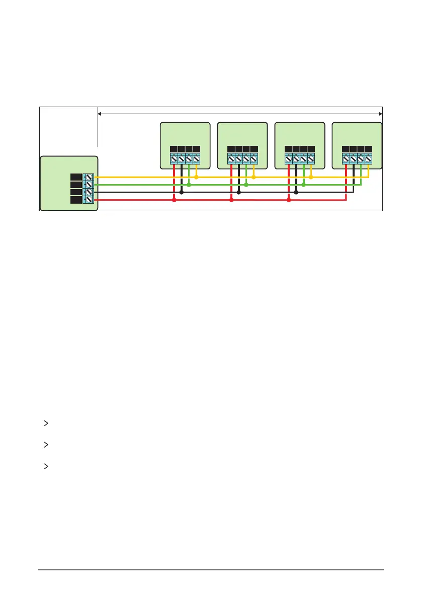
Remote keypads are all connected to the bus terminals located at the bottom left hand corner of
the control panel and may be connected serially (daisy chain), in parallel (star) or any combination
of the two.
Cable Type & Distances
For improved immunity to electrical noise, the use of screened 4 core cable is recommended. The
screen should be twisted together and wired into the (–) terminal at the control panel only.
The maximum recommended distance for devices when using standard 7/0.2 alarm cable is:
100m for each branch when using the star (parallel) configuration.
When using a daisy chain (series) configuration, the maximum distance will depend on the
number of devices connected on the chain. The more devices that are connected, the shorter the
distance to the last device (this is due to voltage drop in the cable).
Whichever method of wiring configuration is used, ensure that the voltage between the '+' and '–'
terminals at each device is no lower than 10.0V when the system is running on the standby
battery.
Overcoming Voltage Drop
There are several ways to overcome voltage drop:
Installing a Power Supply
When a power supply is installed, the 0V connections on the power supply must be connected
through to 0V on the control panel and the +12V connection between the control panel and the
device must be disconnected (see figure on next page).
Up to 100 metres
Remote Keypad
1
Remote Keypad
2
Remote Keypad
3
Remote Keypad
4
R B G Y
R B G Y
R B G YR B G Y
Control Panel
YEL
GRN
BLK
RED
Network
Use thicker lower resistance cable. Standard 7/0.2 alarm cable has a resistance of 8Ω per
100m.
Double up on the power connections – this will require using a 6 or 8-core cable rather than
a 4-core cable.
Install a power supply to power the device locally, remember to common the two negative
connections.
12 Rhino 832 Installation Manual |
 Loading...