Connecting devices to the network
Before connecting devices to the control panel bus, isolate ALL power from the control panel (AC
Mains & Battery). Do not continue if there is still power present on the control panel.
Note: Connecting devices with power still present on the control panel may damage the device
or control panel and invalidate any warranty.
Mounting the control panel
Mount the control panel on a flat, plumb wall using at least three appropriate screws. The rear
casing has been designed with several key-hole slots so that mounting is possible without
removing the Printed Circuit Board (PCB). It is essential to ensure that none of the fixing slots or
cable entries are accessible after fixing.
Installing the expanders
8-zone wired expander
This expander is plugged into the connector of the Rhino 832 PCB as shown on the PCB Layout on
page 9.
16-zone wired expander
The external 16-zone expander connects to the same network terminals as the keypads. These are
located at the bottom left hand corner of the control panel.
Note: The 16-zone expander operates with its own transformer and standby battery.
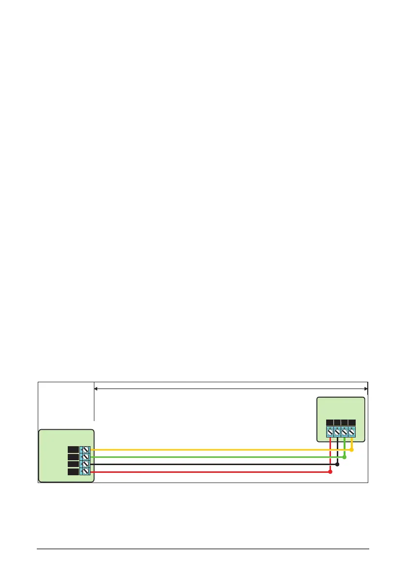
Network Connections
The network is made up of four terminals incorporating power and data. To ensure correct
operation, all four terminals on the device must be connected to the corresponding terminals on
the control panel, or previous device.
Rhino 832 Installation Manual 11 |
Up to 100 metres
16-zone Expander
R B G Y
Control Panel
YEL
GRN
BLK
RED
Network
 Loading...