20
20
GG
BB
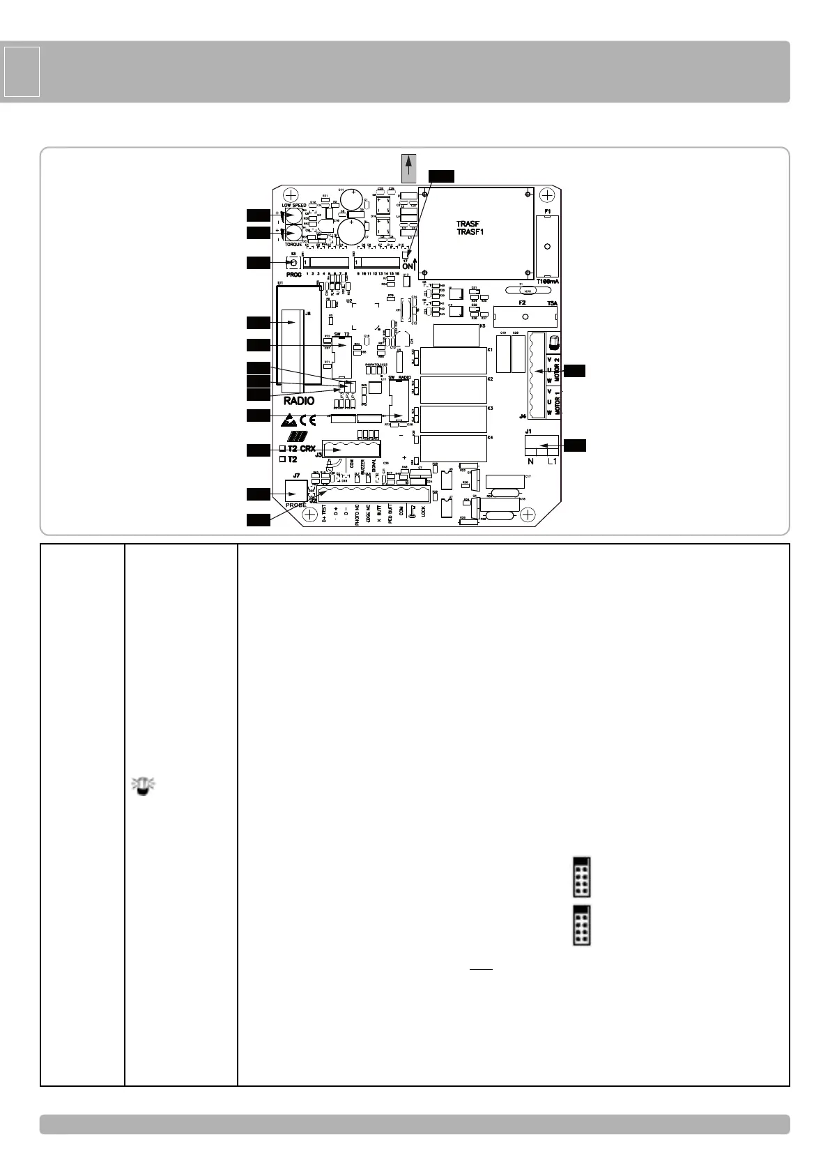
Main power supply 230 Vac 50/60 Hz (120V/60Hz upon request)
Safety strip self-test power supply +12Vdc
Accessories power supply +12Vdc
Accessories power supply -12Vdc
Photocells contact (NC)
Safety strip contact (NC)
Single pulse contact (NO)
Pedestrian opening contact (NO)
Common contact (common line for all the command and safety inputs)
Electric lock connection (MAX 15W 12V)
Radio Antenna
Common contact (common line for all the command and safety inputs)
Buzzer contact (12Vdc max 200 mA)
Gate open state output indicator (12Vdc 3W max)
Flashing light (max 40W )
MOT
OR 2 COMMON CONNECTION
MOTOR 2 PHASE AND CAPACITOR CONNECTIONS
MOT
OR 1 COMMON CONNECTION
MOTOR 1 PHASE AND CAPACITOR CONNECTIONS
DO NOT REMOVE
ANY
JUMPER!
OTHERWISE THE OPERATOR WILL NOT WORK!
(only CRX control board)
DO NOT REMOVE
ANY
JUMPER!
OTHER
WISE THE OPERA
T
OR WILL
NOT WORK!
Terminal block to connect the heater sensor only for operator (code AA14019).
Built-in radio module (model CRX), or connector for radio receiver RIB, 12 Vdc supply
To select 1 motor (M1) or 2 motors (M1 and M2)
Programming button
Electronic torque regulator
Electronic regulator for low speed on approach motor (See chart 1)
J1
J2
J3
J4
J5
J6
J7
J8
JP17
S3
TR1
TR2
N -L1
D+ TEST
D +
D -
PHOT. NC
EDGE NC
K BUTT.
PED. BUTT.
COM
LOCK
AERIAL
COM
BUZZER
SIGNAL
U - MOTOR 2
V-W - MOTOR 2
U - MOT
OR 1
V-W - MOTOR 1
SW
T2
SW RADIO
PROBE
PROG
T
ORQUE
LOW SPEED
POINT A - CONTROL PANEL FEATURES
TR2TR2
TR1TR1
S3S3
J8J8
J5J5
J3J3
J7J7
J2J2
J4J4
J1J1
J6J6
JP1JP1
JP2JP2
JP3JP3
JP17JP17
 Loading...