Do you have a question about the Rice Lake Digi DI-28 and is the answer not in the manual?
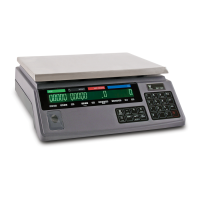
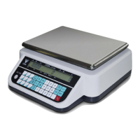
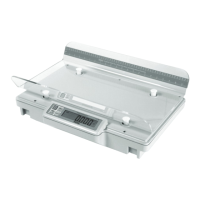
Describes the DI-28 Indicator, its weighing applications, resolution, features, and power sources.
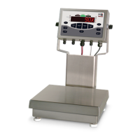
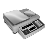
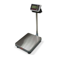
Lists available platforms, their sizes, and capacities for the DI-28 scale.
Details technical specifications including Id Plate, Operating Conditions, Display, and AC/DC Adapter.
Instructions on how to unpack the DI-28 components and inspect them.
Procedure for inspecting the instrument for damage incurred during transportation.
Guidelines for properly repacking the DI-28 for return, modification, calibration, or repair.
Details the procedure for unlocking different styles of platforms for the DI-28 scale.
Information on assembling the optional pole mounting kit for the DI-28 scale.
Procedure to verify proper operation of the scale by connecting power and pressing keys.
Verifies proper operation of switches and displays through Tare Entry tests (One Touch Tare, Digital Tare Entry).
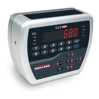
Details the DI-28 scale's control panel, including keys and indicator lamps.
Procedure for powering on the DI-28 scale and initial display sequence.
Explains how to subtract tare weight using one-touch or digital entry.
Procedure to check the remaining battery life indicated by boxes on the display.
Guides users through entering setpoint values using keyboard and specific keys.
Instructions on how to switch between different weight units like KG, g, and lb.
A summary table outlining the functions of each key in different program modes.
Explains how to check the internal count value from the A/D (pre-amp).
Covers setting up and calibrating the DI-28 scale, including specification changes (6.3.1, 6.3.2).
Details W&M specifications (Spec. 00-29) (6.4.1) and operational specifications (Spec. 50-59) (6.4.2).
Procedure for accessing calibration mode to adjust scale span (6.5.1).
Step-by-step guide for performing the scale calibration process (6.5.2).
Checks the status of the Span Switch (JP 1) on the main board.
Explains how the DI-28 can be used with AC/DC adapter or batteries, and charging circuit jumpers.
Describes the setpoint interface, method, and signal output capabilities (7.2.1, 7.2.2, 7.2.3).
Details hardware options like pole sets and mount bracket kits for the DI-28 scale.
Details the RS-232C serial data output, including protocol settings (7.4.1, 7.4.2, 7.4.3, 7.4.4, 7.4.5).
Covers preventive maintenance, including exterior (8.1.1), internal (8.1.2), and accuracy checks (8.1.3).
States that service and repair should only be attempted by qualified personnel.
Details the pin assignments for the Amphenol connector used for load cell wiring.
Outlines RLWS warranty conditions, including notice, packaging, examination, and limitations.
Excludes other warranties and limits liability for incidental or consequential damages.