Do you have a question about the Rice Lake IQ plus 310A and is the answer not in the manual?
General introduction to the indicator's features, capabilities, and installation overview.
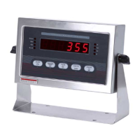
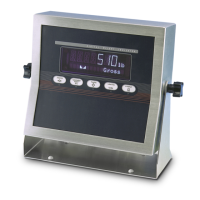
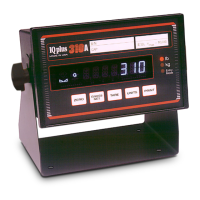
Explains the symbols and indicators displayed on the front panel of the IQplus 310A.
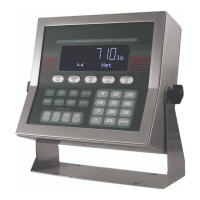
Details the functions of the front panel keys in different operating modes (Operate and Setup).
Introduces the installation section and the logical procedure for hardware setup.
Lists the items included in the accessory kit for installation.
Instructions for safely removing the indicator's case for internal access.
Steps for connecting the power supply, including voltage selection via jumpers.
Guidance on connecting the load cell cable to the main circuit board terminal.
Instructions for connecting serial communication cables to the terminal block.
Instructions for installing capacity, weight unit, and key labels.
Steps for reassembling the indicator case after connections are made.
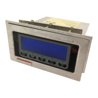
Procedures for mounting the indicator via panel or wall/bench.
Describes the indicator's behavior and display during the power-up sequence.
Lists error codes displayed during power-up and their remedies.
Introduces the configuration section and how parameters are set.
Explains how to navigate the system menus using front panel keys.
Details parameters within the SETUP menu, such as GRADS, DEC PNT, and UNITS.
Configuration options for the digital inputs to duplicate front panel key functions.
Configuration options for the EDP serial port, including mode, baud rate, and format.
Configuration options for the printer port, including mode, baud rate, and format.
Specifies the format for weight tickets sent to the printer or EDP port.
Procedure for performing functional tests and resetting the indicator to default parameters.
Step-by-step guide to calibrating the scale's zero and span.
Instructions for making fine adjustments to span and performing re-zero.
Procedure for installing a legal seal to secure the Operate/Setup switch.
Explains how to use the Auto Tare mode for weighing operations.
Details the operation of the In/Out Tare mode for managing tare values.
Lists and explains error messages displayed by the indicator.
Commands for setting up the indicator via the EDP port.
Commands used for calibrating the indicator through the EDP port.
Commands for operating the scale remotely via the EDP port.
Details serial port operation notes and continuous output data formats.
Lists analog, digital, serial communication, and interface specifications.
Explains the principles of the digital filtering system for reducing vibration effects.
Step-by-step procedure for calibrating the A/D converter.
Details the limited warranty for the IQ plus 310A indicator.
| Brand | Rice Lake |
|---|---|
| Model | IQ plus 310A |
| Category | Accessories |
| Language | English |