Do you have a question about the Rice Lake 880 and is the answer not in the manual?
Explains the meaning of warning, caution, and important symbols used in the manual.
Provides essential safety guidelines for operating and handling the equipment.
Details how to enter configuration mode for setup and calibration.
Details how to modify parameter values using navigation and numeric keys.
Procedure for zeroing the scale, including conditions for success.
How to access and configure setpoint parameters.
Detailed steps for modifying setpoint values.
Procedure to enable or disable setpoints from the front panel.
Details on locating and using the setup switch to enter configuration mode.
Overview of different ways to configure the indicator.
Using the Revolution PC utility for indicator configuration.
Configuring the indicator using its front panel menus.
Explains the steps and options for calibrating the indicator.
Describes configuration options for communication ports like COM, USB, and Ethernet.
Overview of the Setpoint menu structure and available setpoint types.
Detailed parameters for Setpoint Layout A, covering trip, band values, and output configurations.
Configuration options for digital inputs and outputs.
Lists common error messages and their meanings/solutions.
| Brand | Rice Lake |
|---|---|
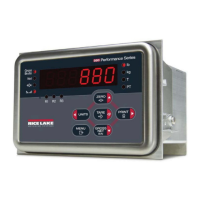
| Model | 880 |
| Category | Accessories |
| Language | English |