April 10, 2017 PN 156858 Rev A
Analog Output Card Installation
PN 179156
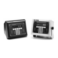
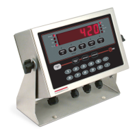
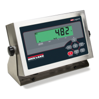
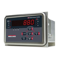
Use the following procedures to install the analog output card in the 880 panel mount and universal desktop model
indicators.
Manuals can be viewed and downloaded
from the Rice Lake Weighing Systems website at www.rlws.com
Table 1-1. Analog Output Card Kit Parts List
Item No. Part Number Description Qty
1 131601 Board Assembly, Analog Output 1
2 14825 Screw, Machine 4-40 NC x 1/4 3
3 181007 Face Plate (Panel Mount Models Only) 1
4 76513 Connector, 4 position Screw Terminal 1
Use anti-static protection for grounding and to protect components
from electrostatic discharge (ESD) when working
inside the indicator enclosure.
Procedures requiring work inside the indicator must be performed by qualified service personnel only.
The supply cord serves as the power disconnect for the 880 Analog Output Installation. The power receptacle to the indicator must
be easily accessible.
Figure 1. Analog Output Card Kit
880 Panel Mount Instructions
1. Disconnect power to the indicator.
2. Unplug all connectors from the backpla
te.
Table 2. 880 Connectors
Connector Type Header Designation
Load Cell J1
Digital I/O J2
Comm 1 J3
USB Micro Device J4
USB Host J5
EtherNet TCP/IP J6
3. Unhook the indicator assembly from the DIN rail by inserting a flat blade screwdriver into the bottom tab
and sliding the mounting plate down (Figure 1 on page 2). Due to the angle of the hook portion of the DIN
bracket, it may be a little tight as it is disconnected.