Do you have a question about the Rice Lake 420 Plus and is the answer not in the manual?
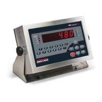
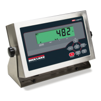
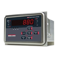
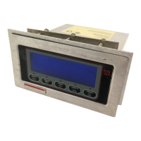
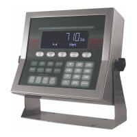
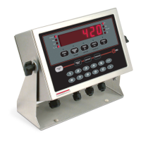
Details the 420 Plus's stainless steel enclosure, display, keypad, and connectivity features.
Explains the four modes: Normal, Piece Count, Setup, and Test.
Illustrates the keypad and describes key functions, especially in setup mode.
Details the eight LED annunciators and their meanings for scale status and units.
Covers core functions like toggling modes, units, zeroing, and taring.
Inspect components upon unpacking and identify parts in the kit.
Instructions for safely opening the indicator enclosure to access internal components.
Guidance on connecting load cells, digital inputs, and communication cables.
Details proper grounding techniques for cables routed through cord grips.
Configuring jumper JMP1 to control power via the AC line.
Recommendations for wiring DC power, including wire gauge and voltage drop.
Procedure for connecting load cell cables to the CPU board connectors.
Details connecting serial communication cables to EDP and printer ports.
Explains digital input and output functions and connection procedures.
Connecting the output cable to the analog output module.
Steps for installing the optional analog output module.
Procedure for reattaching the backplate after cabling is complete.
Detailed steps for removing and reinstalling the CPU board.
Overview of methods: front panel, EDP commands, or Revolution software.
Using Revolution utility for preferred configuration via PC.
Configuring the indicator using EDP commands via PC or terminal.
Navigating menus via front panel keys for configuration.
Explains how to navigate menus and provides descriptions of parameters.
Details parameters for GRADS, ZTRKBN, ZRANGE, MOTBAN, OVRLOA, SMPRAT.
Configures decimal positions, display divisions, and units for primary/secondary displays.
Details primary/secondary units, decimal points, and multipliers.
Overview of calibration parameters: WZERO, WWAL, WSPAN, WLIN, REZERO.
Configures EDP and printer port settings: baud rate, bits, termination.
Sets power-up mode, regulatory mode, UID, date/time formats.
Details regulatory mode, counting mode, accumulator, and date/time settings.
Customizing print formats (GFMT, NFMT, CFMT) using the front panel.
Configures setpoint enable, kind, value, trip, and band values.
Details setpoint enable, kind, value, trip, band value, hysteresis, and access.
Assigns functions to digital inputs 1 and 2.
Configures analog output source, offset, error actions, and min/max values.
Displays software version, register version, and indicator model.
Step-by-step guide for calibrating via the front panel keys.
Calibrating the indicator using EDP commands from a PC or terminal.
Calibrating using the Revolution configuration utility.
Discusses adjusting final calibration and zero deadload A/D counts.
EDP commands that simulate front panel key presses.
Commands to retrieve specific information like parameters or software version.
Restores all configuration parameters to their default values.
Resets the indicator without losing configuration and calibration.
Commands to display or change configuration parameter values.
Commands used to define gross, net, and count print formats.
Procedures for customizing formats via EDP, front panel, or Revolution.
Lists displayed error messages, their descriptions, and solutions.
EDP commands P and ZZ to query indicator status and annunciators.
Format for continuous data sent via EDP or printer port.
Decimal values for ASCII characters used in print format strings.
Continuation of ASCII character values for print formatting.
Shows the 7-segment LED character set used on the front panel display.
Lists multipliers for converting between different units of weight.
Configuring digital filters (DIGFL1-3, DFSENS, DFTHRH) for vibration reduction.
Procedure for fine-tuning filter parameters to optimize performance.
Calibrating the analog output module using a multimeter.
Diagnostic functions including raw A/D count display and parameter reset.
TARE and ZERO key functions based on regulatory mode (NTEP, CANADA, OIML, NONE).
Lists diagnostic LEDs on the CPU board and their operational status.
Detailed specifications for power, analog, digital, serial, and environmental aspects.
| Brand | Rice Lake |
|---|---|
| Model | 420 Plus |
| Category | Accessories |
| Language | English |