EasyManua.ls Logo

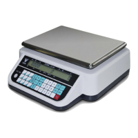
Rice Lake Ishida IPC-WP Series User Manual

Rice Lake Ishida IPC-WP Series
38 pages
To Next Page IconTo Next Page
Page #1 background imageLoading...
Page #1 background image

Questions and Answers:

Rice Lake Ishida IPC-WP Series Specifications

General IconGeneral
DisplayLCD with backlight
Housing MaterialStainless steel
Communication InterfaceRS-232
Power100-240 VAC, 50/60 Hz
Operating Temperature14°F to 104°F (-10°C to 40°C)
Humidity85% RH or less

Summary

Product Overview

Product Overview

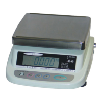
General description of the IPC-WP Series digital scale.

Standard Specifications

Detailed technical specifications including capacity, units, and accuracy.

Appearance Overview

Visual overview of the scale's front, rear, and bottom views.

Operation Panel Layout

Illustrations and descriptions of the operation panels for different specifications.

Outer Dimensions

Technical drawings showing the physical dimensions of the scale.

Test Mode Operations

Test Mode Flowchart

Diagram illustrating the sequence of operations within Test Mode.

Key Functions in Test Mode

Explanation of key functions used during value setting and operation.

Starting and Ending Test Mode

Procedures for initiating and concluding the test mode.

Memory Switch Functionality

Description of the memory switch's role in storing data.

C1 Mode: Country Number Setting

Guide for setting the country number using the C1 mode.

C2 Mode: Scale Number and Decimal Point

Procedure for setting scale number and decimal point indication.

C3 Mode: Span Adjustment

Detailed steps for performing span adjustment in C3 mode.

F Mode: Measuring Conditions and E2ROM Clear

Instructions for setting measuring conditions and clearing E2ROM.

Error Code List

List of error codes, their modes, and descriptions.

Hardware Configuration

Dual Display Mechanisms

Exploded view and parts list for the dual display model.

Single Display Mechanisms

Exploded view and parts list for the single display model.

Electric Concerns: Block Diagram

Overview of electrical components and their interconnections.

Main Board PS-021 Details

Pin assignments and connector details for the main board.

Switch Board PS-022

Information regarding the switch board and its harness.

Dual Display Board PS-023

Details of the dual display board.

Connection Board PS-019

Information on the connection board for power input.

Maintenance Procedures

Case Disassembly and Assembly

Step-by-step guide for disassembling and reassembling the scale case.

Main Board (PS-021) Replacement

Procedure for removing and replacing the main board.

Switch Board (PS-022) Replacement

Steps for replacing the switch board.

Customer Display Board (PS-023) Replacement

Procedure for replacing the customer display board.

Load Cell Replacement

Detailed instructions for replacing the load cell.

Airproof Rubber Ring Replacement

Guide for replacing the airproof rubber ring.

Troubleshooting Common Issues

Symptoms, causes, and measures for common operational problems.

Related product manuals