3. PRODUCT INSTALLATION
-3.1 Installation Precautions
Be very careful when installing the battery. For open lead-acid batteries, wear a pair of goggles during installation, and in case of contact
with battery acid, flush with water immediately.
In order to prevent the battery from being short-circuited, no metal objects shall be placed near the battery.
Acid gas may be generated during battery charging, thus make sure the ambient environment is well ventilated.
Keep the battery away from fire sparks, as the battery may produce flammable gas.
When installing the battery outdoors, take sufficient measures to keep the battery from direct sunlight and rain water intrusion.
Loose connections or corroded wire may cause excessive heat generation which may further melt the wire's insulation layer and burn
surrounding materials, and even cause a fire, therefore make sure all connections are tightened securely. Wires had better be fixed
properly with ties, and when needs arise to move things, avoid wire swaying so as to keep connections from loosening.
When connecting the system, the output terminal's voltage may exceed the top limit for human safety. If operation needs to be done, be
sure to use insulation tools and keep hands dry.
The wiring terminals on the controller can be connected with a single battery or a pack of batteries. Following descriptions in this manual
apply to systems employing either a single battery or a pack of batteries.
Follow the safety advice given by the battery manufacturer.
When selecting connection wires for the system, follow the criterion that the current density is not larger than 4A/mm2.
Connect the controller's earth terminal to the ground.
3/ PRODUCT INSTALLATION
-3.2 Wiring Specifications
Wiring and installation methods must comply with national and local electrical specifications. The wiring specifications of the battery and
loads must be selected according to rated currents, and see the following table for wiring specifications:
!
Warning: risk of explosion! Never install the controller and an
open battery in the same enclosed space! Nor shall the controller be
installed in an enclosed space where battery gas may accumulate.
Warning: danger of high voltage! Photovoltaic arrays may
produce a very high open-circuit voltage. Open the breaker or fuse
before wiring, and be very careful during the wiring process.
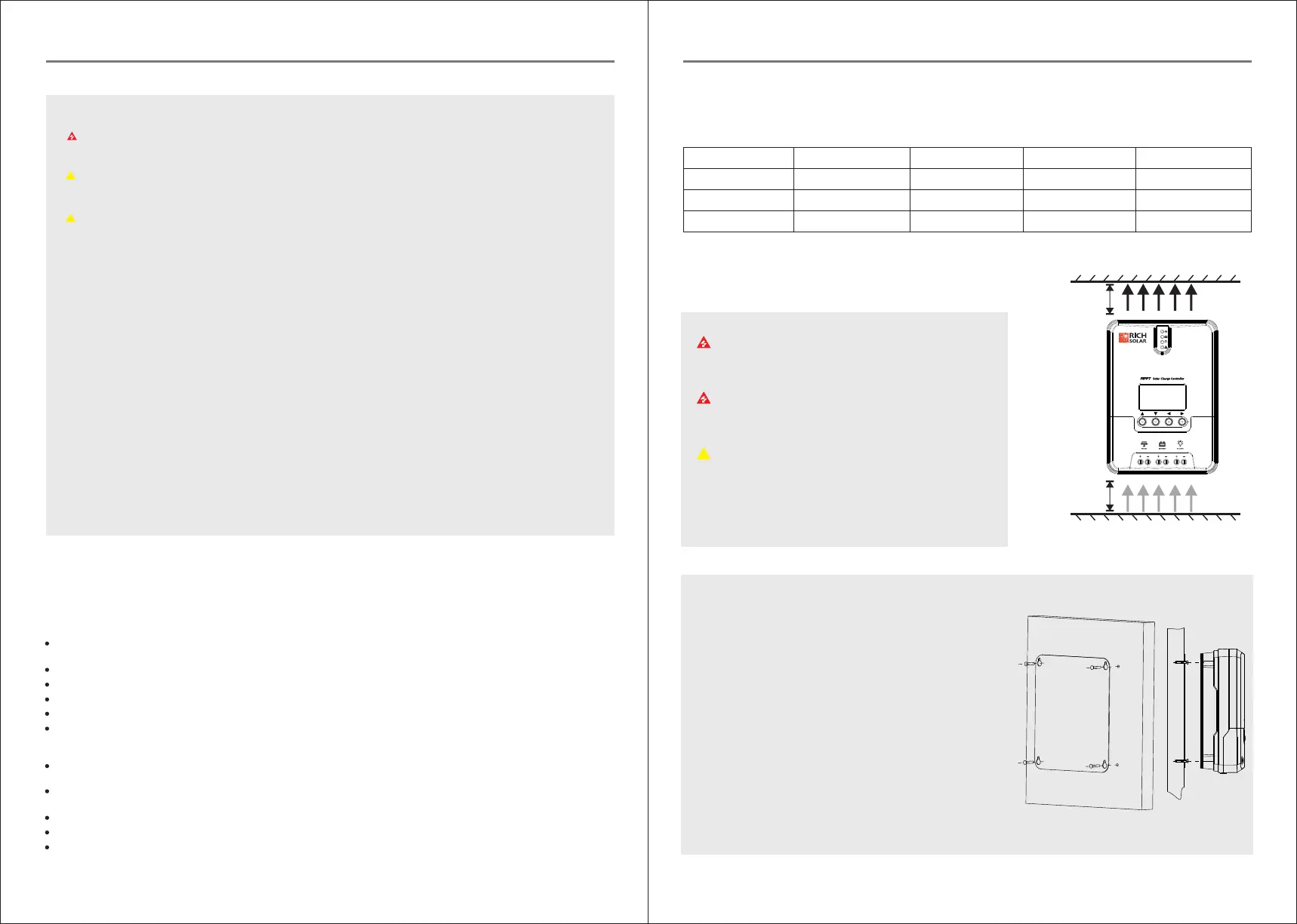
Note: when installing the controller, make sure that enough air
flows through the controller's radiator, and leave at least 150 mm of
space both above and below the controller so as to ensure natural
convection for heat dissipation. If the controller is installed in an
enclosed box, make sure the box delivers reliable heat dissipation
effect.
≥150mm
≥150mm
Hot air
Cold air
Fig. 2.1 Installation and heat dissipation
-3.3 Installation and Wiring
RS-MPPT20
RS-MPPT30
20A
30A
20A
20A
5
5
mm
2
mm
2
5
6
mm
2
mm
2
RS-MPPT40
40A 20A
5
mm
2
10
mm
2
Model
Rated charging
current
Rated discharging
current
Battery wire
diameter (mm )
Load wire
diameter (mm )
2 2
> Equalizing charging
In equalizing charging, an open lead-acid battery can produce explosive gas, therefore the battery chamber shall have good
ventilation conditions.
1) When due to the installation environment or working loads, the system can't continuously stabilize the battery voltage to a
constant level, the controller will initiate a timing process, and 3 hours after the battery voltage reaches the set value, the system
will automatically switch to equalizing charging.
2) If no calibration has been done to the controller clock, the controller will perform equalizing charging regularly according to its
internal clock.
When finishing the sustaining charging stage, the controller will switch to floating charging in which the controller lowers the
battery voltage by diminishing the charging current and keeps the battery voltage at the set value of floating charging voltage. In
the floating charging process, very light charging is carried out for the battery to maintain it at full state. At this stage, the loads
can access almost all the solar power. If the loads consume more power than the solar panel could provide, the controller will not
be able to keep the battery voltage at the floating charging stage. When the battery voltage drops to the set value for returning to
boost charging, the system will exit floating charging and reenter into fast charging.
Note:
> Floating charging
Note: risk of equipment damage!
!
Warning: risk of explosion!
Note: risk of equipment damage!
!
Equalizing charging may raise the battery voltage to a level that may cause damage to sensitive DC loads. Check and make sure
that allowable input voltages of all the loads in the system are greater than the set value for battery equalizing charging.
Overcharge or too much gas generated may damage battery plates and cause active material on the battery plates to scale off.
Equalizing charging to an excessively high level or for too long a period may cause damage. Read carefully the actual
requirements of the battery deployed in the system.
Some types of batteries benefit from regular equalizing charging which can stir the electrolyte, balance the battery voltage and
finish the electrochemical reaction. Equalizing charging raises the battery voltage to a higher level than the standard supply
voltage and gasify the battery electrolyte. If the controller then automatically steers the battery into equalizing charging, the
charging duration is 120 mins (default). In order to avoid too much generated gas or battery overheat, equalizing charging and
boost charging won’t repeat in one complete charging cycle.
0605
Do not install the controller at a place that is subject to direct sunlight,
high temperature or water intrusion, and make sure the ambient
environment is well ventilated.
Step 2: first place the installation guide plate at a proper position, use a
marking pen to mark the mounting points, then drill 4 mounting holes
at the 4 marked points, and fit screws in.
First remove the two screws on the controller, and then begin wiring
operation. In order to guarantee installation safety, we recommend the
following wiring order; however, you can choose not to follow this
order and no damage will be incurred to the controller.
Step 1: choose the installation site
Step 3: fix the controller
Aim the controller's fixing holes at the screws fit in Step 2 and mount
the controller on.
Step 4: wire
3. PRODUCT INSTALLATION
 Loading...