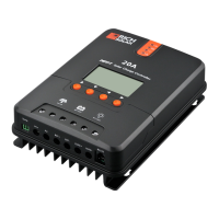
① Connecting to external temperature sampling interface
② Connecting communication cable
③ Connecting power cable
Warning: risk of electric shock! We strongly recommend that fuses or breakers be connected at the photovoltaic array
side, load side and battery side so as to avoid electric shock during wiring operation or faulty operations, and make sure the
fuses and breakers are in open state before wiring.
Warning: danger of high voltage! Photovoltaic arrays may produce a very high open-circuit voltage. Open the breaker or
fuse before wiring, and be very careful during the wiring process.
Warning: risk of explosion! Once the battery's positive and negative terminals or leads that connect to the two terminals
get short-circuited, a fire or explosion will occur. Always be careful in operation.
First connect the battery, then the load, and finally the solar panel. When wiring, follow the order of first "+" and then "-".
④ Power on
After connecting all power wires solidly and reliably, check again whether wiring is correct and if the positive and negative poles
are reversely connected. After confirming that no faults exist, first close the fuse or breaker of the battery, then see whether the
LED indicators light up and the LCD screen displays information. If the LCD screen fails to display information, open the fuse or
breaker immediately and recheck if all connections are correctly done.
If the battery functions normally, connect the solar panel. If sunlight is intense enough, the controller's charging indicator will light
up or flash and begin to charge the battery.
After successfully connecting the battery and photovoltaic array, finally close the fuse or breaker of the load, and then you can
manually test whether the load can be normally turned on and off. For details, refer to information about load working modes and
operations.
Warning: when the controller is in normal charging state, disconnecting the battery will have some negative effect on the
DC loads, and in extreme cases, the loads may get damaged.
Warning: within 10 minutes after the controllers stops charging, if the battery's poles are reversely connected, internal
components of the controller may get damaged.
Note:
1) The battery's fuse or breaker shall be installed as close to the battery side as possible, and it's recommended that installation
distance be not more than 150mm.
2) If no remote temperature sensor is connected to the controller, the battery temperature value will stay at 25 °C.
3) If an inverter is deployed in the system, directly connect the inverter to the battery, and do not connect it to the controller's load
terminals.
3
4
5
6
7
1
2
Temperature sensor
3. PRODUCT INSTALLATION
08
07
4. PRODUCT OPERATION AND DISPLAY
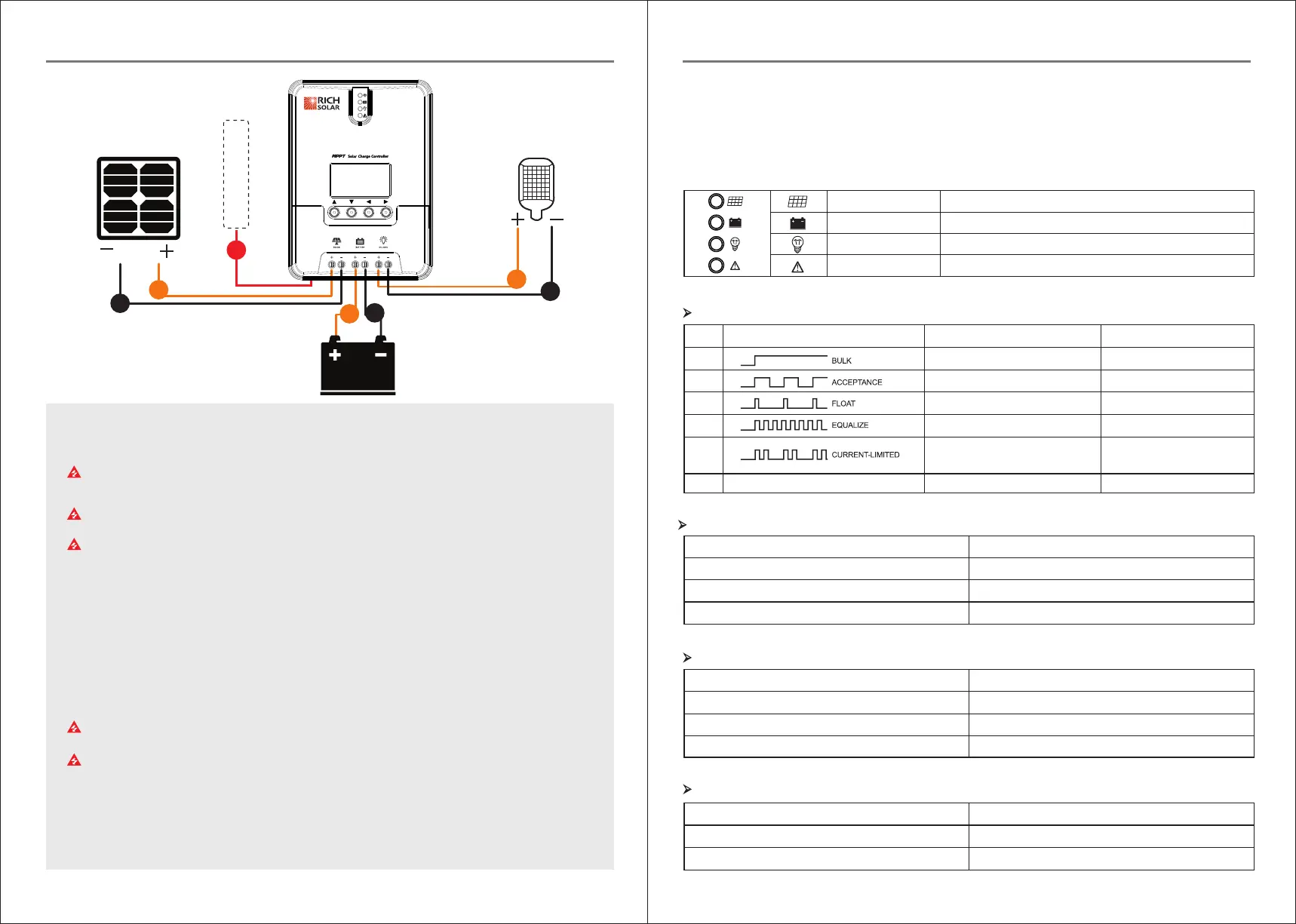
-4.1 LED Indicators
4 / PRODUCT OPERATION AND DISPLAY
PV array indicator:
BAT indicator:
PV array indicator
BAT indicator
LOAD indicator
ERROR indicator
Indicating the controller's current charging mode.
Indicating the battery's current state.
Indicating the loads' On/ Off and state.
Indicating whether the controller is functioning normally.
①
②
③
④
⑤
⑥
Steady on
Slow flashing
(a cycle of 2s with on and off each lasting for 1s)
Single flashing
(a cycle of 2s with on and off lasting respectively for
0.1s and 1.9s)
Quick flashing
(a cycle of 0.2s with on and off each lasting for 0.1s)
Double flashing
(a cycle of 2s with on for 0.1s, off for 0.1s, on again
for 0.1s, and off again for 1.7s)
Off
MPPT charging
Boost charging
Floating charging
Equalizing charging
Current-limited
charging
No charging
No.
Indicator state
Charging state
Graph
Indicator state
Steady on
Slow flashing
(a cycle of 2s with on and off each lasting for 1s)
Quick flashing
(a cycle of 0.2s with on and off each lasting for 0.1s)
Battery state
Normal battery voltage
Battery over-discharged
Battery over-voltage
LOAD indicator:
Indicator state
Off
Quick flashing (a cycle of 0.2s with on and off each lasting for 0.1s)
Steady on
Load state
Load turned off
Load overloaded/ short-circuited
Load functioning normally
ERROR indicator:
Indicator state
Off
Steady on
Abnormality indication
System operating normally
System malfunctioning
 Loading...