5
RICKARD 2019
MLM INTEGRATION WITH BMS
Channel and Zone designations
The Channel number corresponds to the physical (hardware) connection of the field diffusers to the MCU. From
each Power Supply Unit (PSU) a RJ9 data cable connects to a numbered channel on the MCU. During commis-
sioning, diffusers for each control area are linked (zoned) together utilising the MLM Tool application (see MLM
Tool/Help/Getting Started). The number of zones could be from 1 to a maximum of 15 per channel, sequentially
allocated to each master diffuser, with a maximum then of 60 zones per MCU. In practice there will be less than
60 zones as not all diffusers will be designated as master diffusers.
Information between channels can be routed across channels, with a master diffuser on one channel linked to a
slave diffuser(s) on a different channel(s).
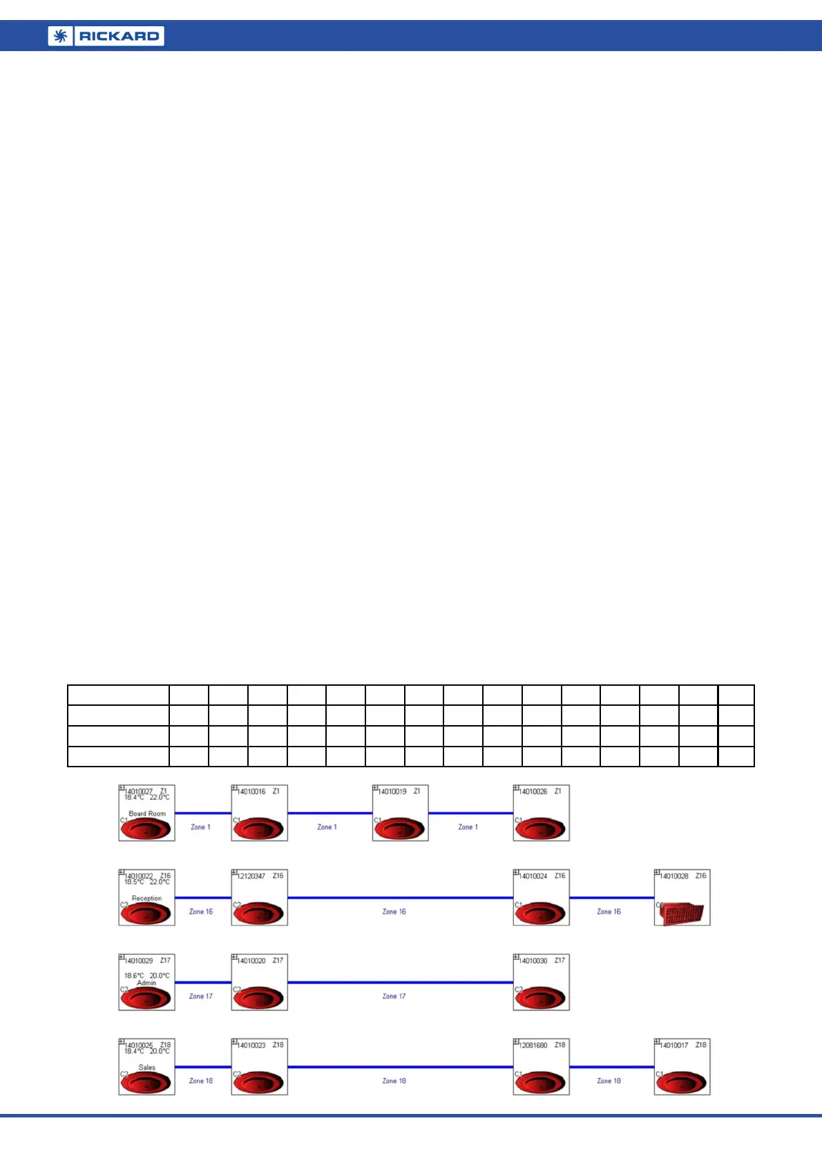
For example, the above layout is designated Zone 16:
Diffuser with serial number 14010022 is connected to channel 2, designated as zone 16 and is set as a master
(temperature reading and setpoint enabled). This diffuser controls the slave diffusers with serial numbers
12120347, 14010028 and 14010024, physically connected to channels 1 and 2.
Note:
It is important to mark the cables from a specific PSU to a specific channel. Swopping cables after com-
missioning will rearrange the data points on the BMS.
The edit and save feature on the application MLM Tool is used to bind the diffusers to their respective
control zones.
Please consult the ‘Making changes to a diffuser network’ section in the MLM Tool rev 8.xx Help file.
During commissioning in edit mode, the user is prompted to allocate zone numbers to diffuser control groups.
These numbers can be arbitrarily allocated to each control zone by the user. Once the save button is pressed,
the application will automatically allocate sequential zone numbers to the project. Zone numbers will be allocat-
ed 15 per channel, with channel 1 starting with Zone 1 up to a maximum of Zone 15. Channel 2 will start with
Zone 16, irrespective of channel 1 taking up 15 control zones or not. By the same token the channel 3 zone
numbers will start at 31 and channel 4 starts at zone number 46.
The 3 zone numbers marked in bold in the table below corresponds to the physical connection to channel 1
(Zone 1) and channel 2 (Zones 16, 17 & 18) as depicted in the logical diffuser layout (below) in the MLM Tool.
Channel 1
Z1
Z2 Z3 Z4 Z5 Z6 Z7 Z8 Z9 Z10 Z11 Z12 Z13 Z14 Z15
Channel 2
Z16 Z17 Z18
Z19 Z20 Z21 Z22 Z23 Z24 Z25 Z26 Z27 Z28 Z29 Z30
Channel 3 Z31 Z32 Z33 Z34 Z35 Z36 Z37 Z38 Z39 Z40 Z41 Z42 Z43 Z44 Z45
Channel 4 Z46 Z47 Z48 Z49 Z50 Z51 Z52 Z53 Z54 Z55 Z56 Z57 Z58 Z59 Z60