6
RICKARD 2019
MLM INTEGRATION WITH BMS
Identifying, mapping and binding of network variables to other network protocols
MCU to Lon Mapping
To connect with the MLM Tool to a Lon configured MCU, the USB type B hardware port on the MCU 2 is used.
Either ‘Basic View’ or ‘Project View’ can be selected in the MLM Tool application.
For Basic View access press the connect button and select the MSTP tab. The diffuser network will be displayed.
The MLM Tool can now be used to set up and commission the diffuser network.
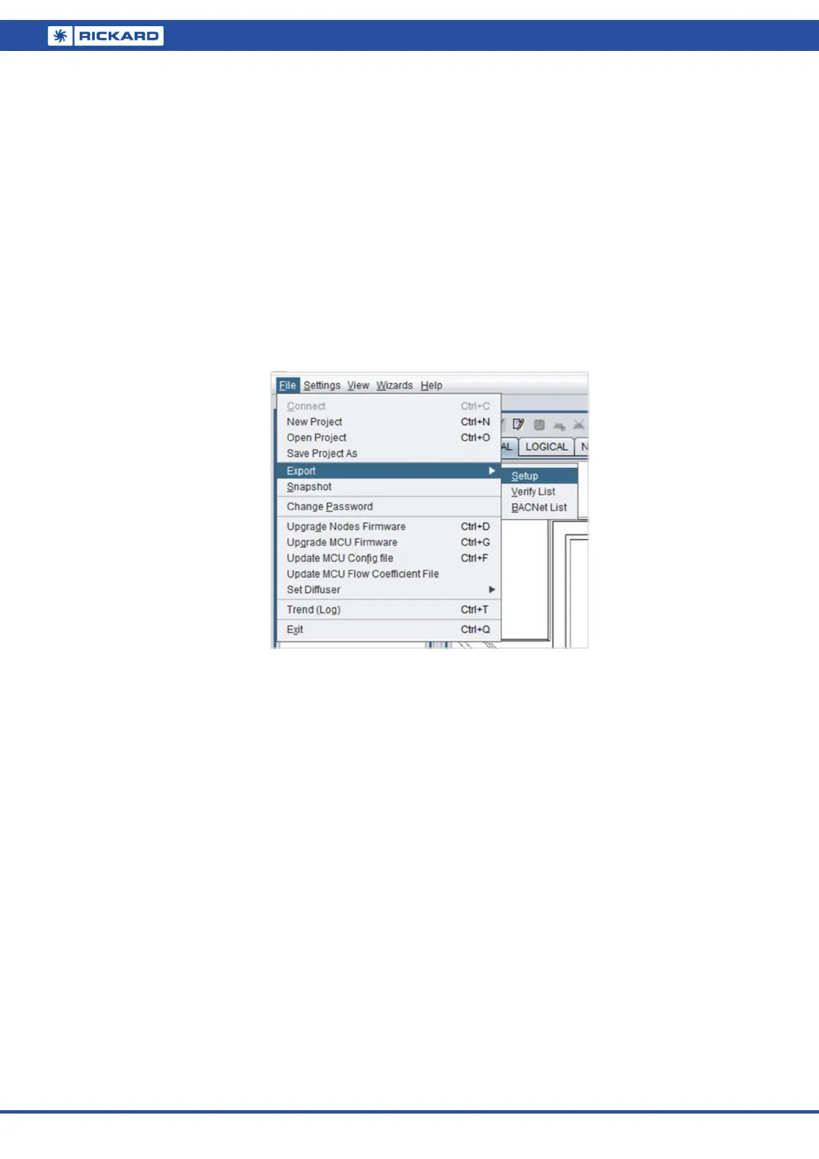
By using the File/Export Setup command, a list can now be exported to a tab delimited text file of all the master
diffusers in the MLM proprietary network. Note that although it is not essential to extract a ‘master’ list, it is a
handy tool to link the zone, serial number and DeviceName (location) fields.
Be sure to select the ‘Master Only’ box to identify the point reference for the BMS.The table is exported in the
following text format:
Description:
Connection Address: MSTP-USB
Exporting only masters
Channel Type ID HID Loop ChLpMap LonStr Zone Code Serial Nr Firmw DevName
1 Diff 6 6 1 17 [1] 1 1 BT20 14010027 0608 Boardroom
2 Diff 2 2 1 33 [2] 1 1 BT20 14010022 0608 Recepon
2 Diff 6 6 2 34 [2] 2 17 BT20 14010029 0608 Admin
2 Diff 4 4 3 35 [2] 3 18 BT20 14010025 0608 Sales
The fields of interest are:
Type – ‘Diff’ indicates the diffuser controller hardware and in conjuncon with the ‘Serial Nr’ field idenfies
the actual diffuser selected as master for that control zone.
LonStr – Indicates the [channel][loop number] of the physical hardware point. This is legacy informaon and
can be ignored.
ChLpMap – Decimal presentaon of the LonStr indicator. Legacy informaon.
Devicename – Physical locaon in the building of the control zone. It is strongly recommended that this 12
character (Device name + Device name ext) identy string is implemented during commissioning.