OCP (Over Current Protection)
Can only be enabled by Panel buttons (“SHIFT” + “I-SET”)
IF the Output Current exceeds, the set value:
● Unit will enter Protection Mode.
● The output will immediately turn OFF, upon entering Protection Mode.
(See Notes: **)
○ (versus the RD60xx unit adjusting output to maintain the ‘I-Set’ value.)
● The “ON/OFF” Button will turn off its illumination,
○ or react per the setting of ‘External LED’.
● The Current measurement value will be changed to the ‘OCP’ display colour.
○ See ‘Colours Group’ Detailed Explanation
● The Normal Operating Mode indicator is replaced by a red background white
‘OCP’ Icon.
Notes:
- Disabled by setting to 0.
- When Setting, “SHIFT” button will be illuminated to visually distinguish an ‘OCP’ input
from an ‘I-SET’ input.
- ** OCP is controlled via firmware, not hardware **.
- As a result, there could be a delay of up to 600ms between the Current reaching
the set value and the RD60xx going into Protection Mode.
- Should be set to a higher value than ‘I-Set’ for proper operation.
- See ‘ISET > OCP+200’ for an Advanced Option that allows this situation.
- Setting OCP lower than I-SET is typically not a good idea.
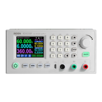
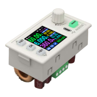
- It was done for the example image, below, to deliberately trigger OCP.
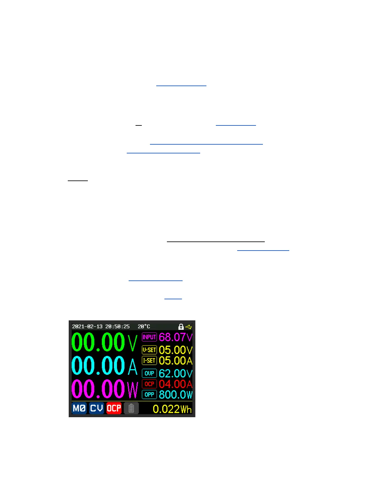
Example Screen Image of OCP Protection activated