Chart B lists the minimum length of pipe or tubing to be
grooved and the maximum length to be grooved with
one (1) RJ624 Pipe Stand.
Pipe Set-Up
1. Pipe or tubing longer than the specified maximum
lengths listed in
Charts A & B
must be supported
with two (2) pipe stands. If only one stand is used, the
pipe should be centered on the stand so that the
pipe’s center of gravity is over the center of the stand.
Failure to use two stands may result in
unit tipping or the pipe falling. Make sure stands and pipe
are stable.
2. Raise upper groove roll housing by placing pump
release lever in RETURN position.
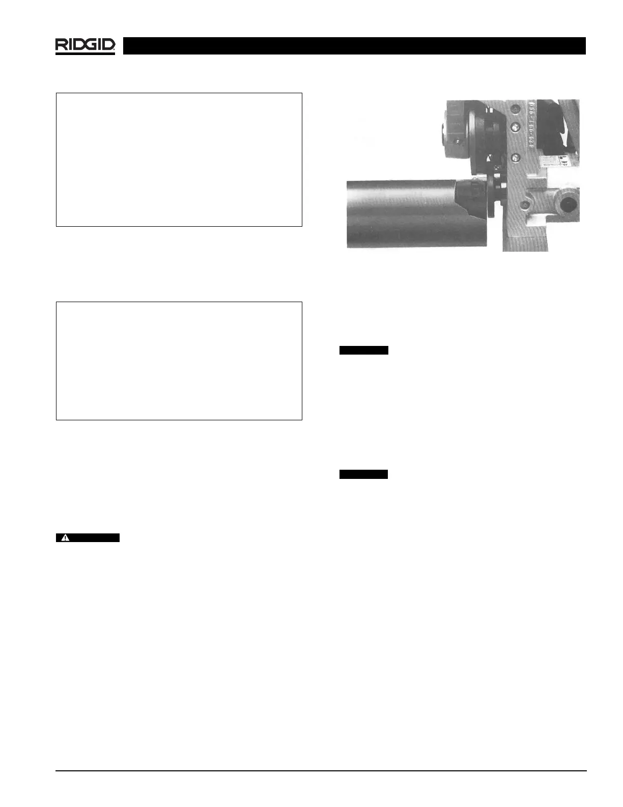
3. Square pipe and pipe support to roll groover making
sure pipe is flush against drive roll flange.
(Figure 9)
Figure 9 – Close-Up of Pipe Against Drive Roll Flange
4. Verify that the pipe is level or sloped slightly upward
away from the operator.
NOTE! If the machine cannot be leveled, make sure
that the slope of the pipe and the machine are
the same.
If pipe is grooved with free end of pipe (end of
pipe which is not in tool) too much higher than the end
being grooved, pipe may not track and pipe end flare may
result. Pipe exceeding fitting manufacturer’s recom-
mended flare specifications may prevent assembly of
couplings pad-to-pad, allowing possible pipe separation,
and result in property damage. Also, joint leakage may
result due to excessive gasket distortion/damage.
5. Check that the pipe is square with the drive shaft or
tilted upward
1
/
2
° from the operator.
“Tracking Angle” will affect pipe end flare
(Figure 10)
. When pipe end flare is excessive, left-to-right
tracking angle must be kept to a minimum. It may be
necessary to use an angle less than
1
/
2
º.
920 Roll Groover
Ridge Tool Company 9
Groovable Pipe Lengths – Inches
Nom. Min. Max. Nom. Min. Max.
Size Length Length Size Length Length
1 8 36 4 8 36
1
1
/
4
8364
1
/
2
832
1
1
/
2
836 5 832
2 8 36 6 O.D. 10 30
2
1
/
2
8 36 6 10 28
3836
3
1
/
2
836
Chart A – Minimum/Maximum Pipe Length – 1″ to 6″ O.D.
Groovable Pipe Lengths – Inches
Nom. Min. Max. Nom. Min. Max.
Size Length Length Size Length Length
8 O.D. 10 96 16 12 96
81096181296
10 10 96 20 12 96
12 12 96 22 12 96
14 12 96 24 12 96
16 12 96
Chart B – Minimum/Maximum Pipe Length – 8″ to 24″ O.D.
CAUTION
CAUTION
WARNING