Ridge Tool Company/Elyria, Ohio, U.S.A.
2
975 Combo Roll Groover
Groove and Drive Roll Set Change-out Instructions
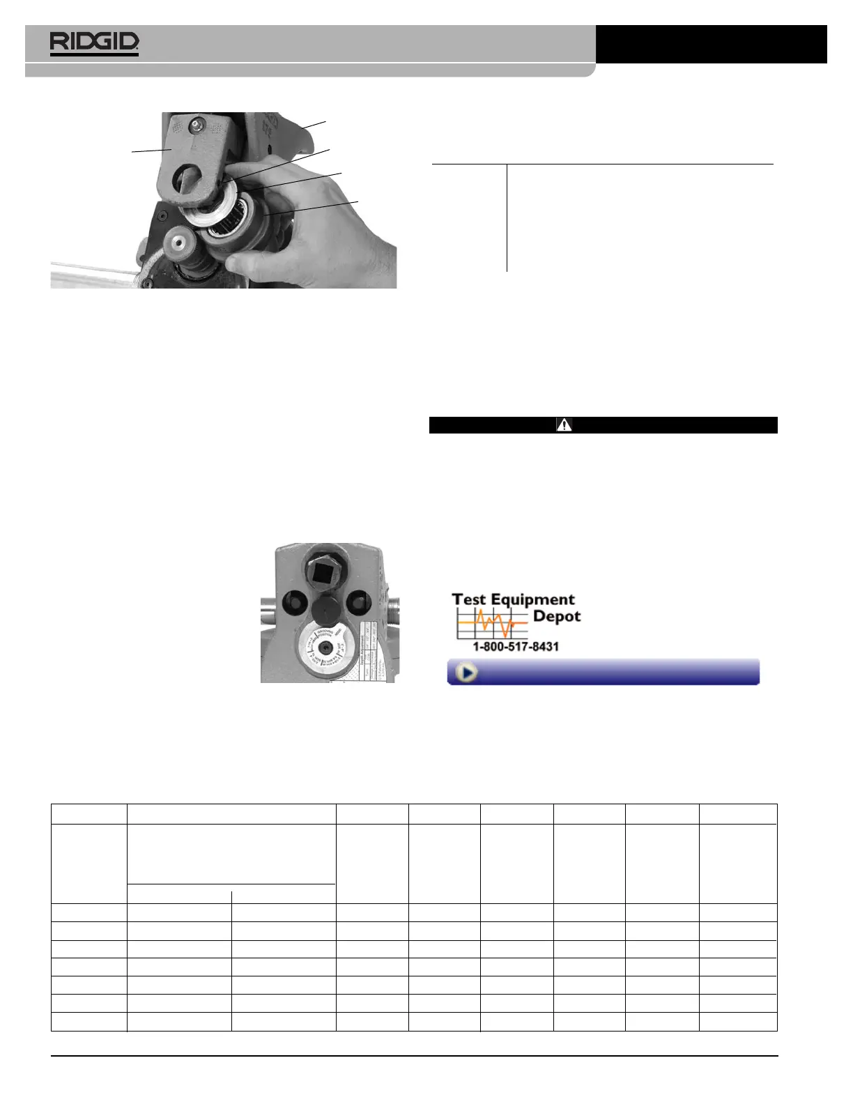
Figure 4
6. Grease as directed in
Lubrication Section
of manual.
Setting The Groove Diameter For Copper
Tubing
When using the 975 Combo Roll Groover for copper tube,
the groove depth gauge on the groover cannot be used. It
will give incorrect groove diameters.
1. Turn the feedscrew clockwise to bring the groove roll
down in contact with the pipe outside diameter, then turn
the feedscrew one quarter additional turn. The adjust-
ing screw may need to be loosened (turned counter-
clockwise) to allow the groove roll to contact pipe. The
pipe and roll groover should be se cure to each other at
this point.
2. Make sure the groove depth
gauge is in the grooving po -
sition.
(Figure 5)
3. Turn the adjusting screw until it
is flush with the top plate of
the groover.
4. Find the diameter and type of
pipe to be grooved on Table A
and back the adjusting screw
off the top plate the corre-
sponding number of turns. For example, for 4" Sch. L
copper, back the adjustment screw 1
1
/
4
turns.
5.
Go to step 4 of “Setting/Measuring The Groove Dia -
meter” in the 975 Combo Groover operator’s manual. In
step 6 use the Copper Roll Groove Specifications.
Service and Repair
WARNING
Improper ser
vice or repair can make machine unsafe
to operate.
Tool should be taken to a RIDGID Independent Author ized
Service Center or returned to the factory.
When servicing this machine, only identical replacement
parts should be used. Use of other parts may create a risk
of serious injury.
Chart A – Depth Adjustment for Roll Grooving Copper
Tubing
Depth Adjustment for Roll Grooving Copper Tubing
(Adjusting Screw Turns)
Dia. K L M DWV
2-2.5"
7
/
8
7
/
8
5
/
8
5
/
8
3" 1
1
/
16
1
1
/
16
1
1
/
16
1
1
/
16
4" 1
1
/
4
1
1
/
4
1
1
/
4
1
1
/
8
5" 1
1
/
2
1
1
/
2
1
1
/
2
1
1
/
2
6" 1
13
/
16
1
3
/
4
1
3
/
4
1
3
/
4
8" 2
1
/
2
2
3
/
8
2
1
/
8
2
1
/
8
Figure 5 – Gauge In
Grooving Position
Table I. Copper Roll Groove Specifications
1 2 345678
AB CDT
Nom. Tubing Outside Gasket Groove Groove Groove Min. Max.
Size Diameter O.D. Seat Width Dia. Depth Allow. Allow.
Inches A +.03 +.00 Ref.
1
Wall Flare
Basic Tolerance ±0.03 –.000 –.02 Thick. Dia.
2" 2.125 ±0.002 0.610 0.300 2.029 0.048 DWV 2.220
2
1
/
2
" 2.625 ±0.002 0.610 0.300 2.525 0.050 0.065 2.720
3" 3.125 ±0.002 0.610 0.300 3.025 0.050 DWV 3.220
4" 4.125 ±0.002 0.610 0.300 4.019 0.053 DWV 4.220
5" 5.125 ±0.002 0.610 0.300 5.019 0.053 DWV 5.220
6" 6.125 ±0.002 0.610 0.300 5.999 0.063 DWV 6.220
8" 8.125 +0.002/-0.004 0.610 0.300 7.959 0.083 DWV 8.220
1. Nominal Groove Depth is provided as a reference dimension. Do not use groove depth to determine groove acceptability.
Main Housing
Set Screw
Thrust
Washer
Groove
Roll
Slide
Block
99 Washington Street
Melrose, MA 02176
Phone 781-665-1400
Toll Free 1-800-517-8431
Visit us at www.TestEquipmentDepot.com
 Loading...