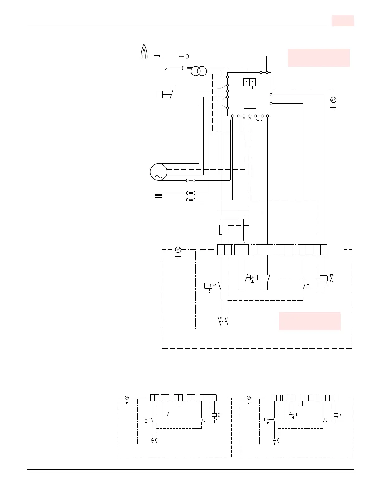
Wiring legend
C - Capacitor MV
F - Fuse 6.25A
CN... - Connectors
MV - Motor
PA - Air pressure switch
Pc - Valve source interlock
PS - Remote lock-out signal
SO - Ionization probe
TA - Ignition transformer
TB - Burner earth
TR - Limit thermostat
TS - Safety thermostat
T6A -Fuse
V1 - Gas valve
X12 - Terminal board 12 pole
White
Blue
Brown
Black
D7422
CONTROL CIRCUITS
Burner operation may be controlled by
either 120V or 24V control systems.
The required controls must be con-
nected to the burner as described on
the following.
120V CONTROL SYSTEM
The burner provides it own power sup-
ply for the control circuits that is
switched internal from terminal 1(L) &
2 (N), do not apply power on any other
terminal or damaged to the control
could occur.
The factory-installed jumper can be
removed if a P.O.C device is desired.
24V CONTROL SYSTEM
If firing is to be controlled by a 24V
operating system a 24V switching
relay wired as shown in the diagram is
required (not supplied – sold sepa-
rately).
The required 24V operating controls
must be wired between the thermostat
terminals on the 24V-switching relay.
The factory-installed jumper can be
removed if a P.O.C device is desired.
NOTE
If an external electrical source is uti-
lized, the conversion burner, when
installed, must be electrically grounded
with a solid green wire to Earth
Ground, in accordance with local
codes or, in the absence of local
codes, with the National Electrical
Code ANSI/NFPA 70-1990 and the
CSA Electrical Code.
120V CONTROL SYSTEM 24V CONTROL SYSTEM
D7492 D7493
Jumper Jumper
TO BE DONE BY
THE INSTALLER
CARRIED-OUT
IN THE FACTORY
 Loading...