GB
20027974
10
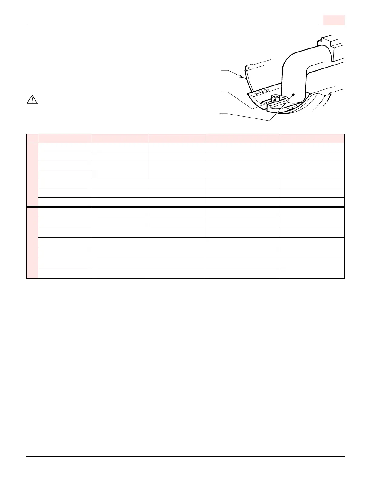
COMBUSTION HEAD SETTING
To set combustion head, loosen the Allen screw (A) and move the
elbow (B) so that the rear edge of the air tube (C) coincides with the
set point number.
See firing rate chart for set points.
Retighten the Allen screw (A).
BURNER SETUP CHART
1) All tests were performed with 0” wc chamber pressure
2) Line pressure measured at test point before burner regulator.
NOTE:
The above settings are a starting point for adjustments ONLY; a qualified gas technician using proper test equipment
must do the final adjustments.
Proper CO
2
, O
2
, and CO readings must be taken and be within regulating code requirements.
All the settings above are based on zero (0) over fire-draft.
If positive or negative chamber conditions exist some settings changes made be required.
For any referral to valve setting, please check the attached manufacturer valve specification.
BTU Input Air Gate Stop Gate Manifold Pressure Line Pressure
NATUARAL GAS
250,000 1.1 0.0 1.00 1.37
350,000 2.0 0.0 2.00 2.70
450,000 2.5 1.0 1.87 3.10
550,000 2.9 2.0 1.75 3.45
650,000 4.0 3.0 2.05 4.35
750,000 5.0 4.0 2.45 5.35
900,000 9.0 5.0 3.35 7.75
PROPANE
250,000 1.20 0.0 1.23 1.40
350,000 2.00 0.0 2.25 2.53
450,000 2.40 1.0 2.15 2.60
550,000 3.20 2.0 2.8 3.63
650,000 4.25 3.0 3.2 4.30
750,000 5.25 4.0 4.2 5.65
900,000 8.00 5.0 5.2 6.90
Make sure you are using the correct table for either
Natural gas or Propane gas.
 Loading...