58
RECYCLING AND DISPOSAL
58
APPENDIX
APPENDIX
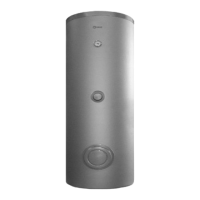
Layout 3: circuit with boiler connected to a heating system via a separator
8 7
2
11
RI
1
11
11
OS
10
5
6
4
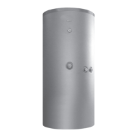
Layout 4: circuit with boiler linked to Indirect DHW tank and heating system via a separator
4
10
11
8 7
EAF
MI
2
11
RI
1
11
OS
12
1
UAC
3
EAF
4
M
2 7
8
1 1
1
1
9
5
6
5
6
6
5
6
OS Outdoor temperature
sensor
MI High temperature system
supply
RI High temperature system
return
EAF Domestic cold water inlet
UAC Domestic hot water outlet
9
WARNING: Domestic hot water and central heating circuits must be completed with expansion tanks of adequate capacity and suit-
ability, correctly-sized pressure relief valves. The discharge of pressure relief valves and appliances must be connected to a suitable
collection and disposal system.
9
CAUTION: The choice of system components and the method of their installation are left up to the heating engineer installing the
system. Installers must use their expertise to ensure proper installation and functioning in conformity to all applicable legislation.
9
CAUTION: Special supply/rell water must be conditioned using suitable treatment systems.
0
WARNING: It is prohibited to operate the boiler without water.
1 Isolating valve
2 Check valve
3 Anti-scald mixing valve
4 Expansion tank
5 Pressure relief valve
6 Drain
7 Water softener lter
8 Pressure reducer
9 Domestic water storage tank
10 Pump
11 High-temperature system circulator
12 Indirect tank circulator