EasyManua.ls Logo

Riello Array AR 399 SE - User Manual

Riello Array AR 399 SE
84 pages
To Next Page IconTo Next Page
Loading...
cod. 20183248 rev. 2
04/2021
9
WARNING: If the information in this manual is not
followed exactly, a fire or explosion may result causing
property damage, personal injury or loss of life.
Do not store or use gasoline or other flammable
vapors and liquids or other combustible materials in
the vicinity of this or any other appliance. To do so
may result in an explosion or fire.
What to do if you smell gas:
- Do not try to light any appliance;
- Do not touch any electrical switch; do not use any
phone in your building;
- Immediately call your gas supplier from a neighbor’s
phone. Follow the gas supplier’s instructions;
- If you cannot reach your gas supplier, call the fire
department.
Installation and service must be performed by a
qualified installer, service agency or the gas supplier.
This manual should be maintained in legible
condition and kept adjacent to the boiler or in a safe
place for future reference.
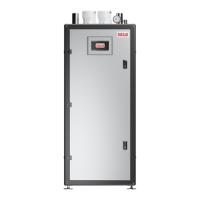
Commercial Boilers
AHRI Standard BTS-2000
Array AR 399 SE - 500 SE
INSTALLATION, OPERATION AND SERVICE MANUAL

Table of Contents

Questions and Answers

Riello Array AR 399 SE Specifications

General IconGeneral
BrandRiello
ModelArray AR 399 SE
CategoryWater Heater
LanguageEnglish

Summary

1 GENERAL INFORMATION

1.1 Key to symbols

Explains symbols used in the manual to convey important information and warnings.

1.2 General Safety Information

Outlines essential safety precautions and responsibilities for installers, operators, and owners of the boiler.

1.3 Warnings

1.3.1 General warnings

Provides critical safety warnings regarding gas, overheating, water submersion, and environmental hazards.

2 PRODUCT DESCRIPTION

2.1 Description of the appliance

Describes the Array AR SE as a condensing thermal module with key technical features like heat exchanger and control.

2.2 Safety devices

Lists the electronic safety devices installed on the CH water circuit and combustion circuit for safe operation.

2.3 Proper Use

Defines the intended use of Array boilers for residential, commercial, and industrial applications in closed loop systems.

2.4 Environmental Responsibility; Disposal

Outlines the company's commitment to environmental responsibility and the recyclability of packaging materials.

2.5 Emergency Shutdown

Describes the procedure for emergency shutdown, including closing the manual gas shutoff valve.

2 PRODUCT DESCRIPTION

2.6 Prolonged Shutdown

Explains procedures for startup after prolonged shutdown and emergency shutoff, including specific Massachusetts regulations.

2 PRODUCT DESCRIPTION

2.7 Identification

Details how products are identified, focusing on the data plate and its importance for installation and servicing.

2 PRODUCT DESCRIPTION

2.8 System layout

Illustrates the system layout of the Array AR SE boiler with numbered components for identification.

2 PRODUCT DESCRIPTION

2.9 Dimension

Provides dimensional drawings of the Array AR SE boiler, showing width, height, and depth.

2 PRODUCT DESCRIPTION

2.10 Technical specifications

Lists detailed technical specifications for the AR 399 SE and AR 500 SE models, including input, output, and connections.

2 PRODUCT DESCRIPTION

2.11 Efficiency Curves

Presents thermal efficiency curves for the Array AR 399 SE and 500 SE boilers based on return water temperature.

2 PRODUCT DESCRIPTION

2.12 Pumps

Describes the built-in circulator with an integrated check valve and precautions for its operation.

2.13 Water circuit

Illustrates the water circuit of the boiler, identifying key components like the heat exchanger and pump.

2.14 Positioning of the temperature sensors

Shows the location of various temperature sensors within the boiler for accurate monitoring.

2 PRODUCT DESCRIPTION

2.15 Service panel

Explains the function of the control panel buttons and displays, including navigation and symbols for operation.

2 PRODUCT DESCRIPTION

2.16 Regulations and Guidelines

Details compliance with national and local standards like ANSI Z223.1/NFPA 54 and CSA B149.1.

2.16.1 Compliance with standards and regulations

Details compliance with national and local standards like ANSI Z223.1/NFPA 54 and CSA B149.1.

2.16.2 Operating limits of the boiler

Specifies the operating limits and ASME code compliance for the heat exchanger and hot water distribution system.

2.16.3 Additional regulations for installations in the Commonwealth of Massachusetts

Outlines specific Massachusetts regulations for side wall vented gas equipment, including CO detectors and signage.

3 INSTALLATION

3.1 Introduction

Introduces the chapter's purpose: guiding the unpacking, inspection, and installation of the RIELLO Array Boiler.

3.2 Receiving the Unit

Provides instructions on how to receive the boiler unit, emphasizing inspection for shipping damage before signing.

3.3 Unpacking

Guides on carefully unpacking the unit, inspecting for damage, and identifying standard accessories.

3.4 Site Preparation

Details requirements for the installation site, including power access, gas line, and location relative to drains.

3.5 Installation premises

Specifies that the boiler can be installed in rooms with adequate ventilation and outlines necessary clearance for safety and maintenance.

3.5.1 Installation clearances

Lists recommended minimum clearances for installation and servicing around the boiler unit.

3 INSTALLATION

3.5.2 Setting the Unit

Explains how to remove packaging, secure the unit, and position it correctly on the floor.

3 INSTALLATION

3.6 Installation in older systems and systems requiring modifications

Provides checks for installing boilers in older systems, focusing on flue, electrical, fuel lines, and pump suitability.

3.7 Boiler Location

Specifies indoor installation requirements, clean air supply, and avoiding freezing or flammable vapor locations.

3.8 Water Quality Guidelines

Lists acceptable water quality parameters to prevent lime buildup and corrosion in stainless steel heat exchangers.

3 INSTALLATION

3.9 ASME pressure relief valve

Details the operation, maintenance, and safety of the ASME pressure relief valve, emphasizing annual testing.

Maintenance of the relief valve

Details the operation, maintenance, and safety of the ASME pressure relief valve, emphasizing annual testing.

3 INSTALLATION

3.10 Condensate Drain and Piping

Describes how to fill the condensate system and syphon, and the need for proper drainage and neutralization.

3.11 Water connection

Guides on connecting the boiler to the system, emphasizing cleaning the system and using protective fluids.

3.12 Gas connections

Outlines requirements for gas connections, including fuel type suitability, clean piping, and code compliance.

3 INSTALLATION

3.13 Combustion gas exhaust

Specifies the use of approved pipes for flue gas exhaust and combustion air intake, and warnings about mixing systems.

3 INSTALLATION

3.14 Gas Type Conversion

Explains the process for converting the unit from natural gas to propane, requiring a qualified technician and specific kits.

3 INSTALLATION

3.15 Adjusting and Setting 02 Limits

Details the procedure for adjusting and setting O2 limits using a combustion analyzer for optimal combustion.

3 INSTALLATION

3.16 Wiring diagram

Provides a detailed wiring diagram for the boiler's control board, including component identification and cable colors.

3 INSTALLATION

3.17 Electronic control

Explains the multi-level electronic control interface, guiding navigation and parameter access.

3.17.1 Menu structure

Maps out the multi-level menu structure of the electronic control panel, guiding navigation and parameter access.

4 COMMISSIONING

4.1 Introduction

Emphasizes the installer's role in instructing the user on boiler operation, safety, and manual usage.

4.2 Filling the Condensate System

Instructs on filling the condensate system and syphon with water to prevent combustion gas leakage.

4.3 Filling the Boiler Heating System

Provides a step-by-step guide for filling the heating system and boiler, including checking pressure and leaks.

4.4 Warnings Concerning the Gas Supply

Highlights crucial warnings regarding gas supply, including type confirmation and conversion procedures.

4.4.1 Confirming the Units Gas Type

Advises checking that the unit is supplied with the correct gas type and pressure as per the rating label.

4.4.2 Gas Type Conversion

Explains that conversion kits are available for different gas types and must be performed by a qualified technician.

4.5 Boiler Startup Procedure

Outlines the steps for initial boiler startup, including opening valves, turning on power, and checking the control panel.

4 COMMISSIONING

4.5.1 Minimum Water Flow (Heat Exchanger Protection)

Explains the self-protection mechanism against low water flow, where the burner shuts off automatically.

4.5.2 Heating System Pressure Test

Details how to perform a heating system pressure test, checking the gauge and restoring pressure if it drops.

4 COMMISSIONING

4.6 Multiple Boiler Cascade Installation and Start-Up

Describes the capability of the control system to manage multiple boilers in a cascade for coordinated heating.

5 OPERATION

5.1 Introduction

Introduces the chapter on operating the Array AR SE boiler using the front control panel.

5.2 Control Panel Description

Describes the touchscreen control panel and its function for monitoring and basic setup of the boiler.

5.3 Touchscreen Control Panel Menu

Explains the structure of the control panel menu for monitoring and setting up the unit.

5.3.1 Riello Screen

Identifies the RIELLO logo screen as the entry point to the control system.

5.3.2 Module Screen

Explains the Module screen, showing plant configuration and actions like adjusting setpoints or accessing other menus.

5 OPERATION

5.3.3 Performance Screen

Shows real-time performance data of the plant over the last 10 minutes, including temperatures and flame status.

5.3.4 Service Screen

Displays parameters related to the Service Reminder function, including service history and interval settings.

5.3.5 Test Screen

Details the Test screen, designed for installers to perform tests on various boiler functions like ignition and high limit.

5 OPERATION

5.3.6 Cascade Screen

Displays the screen for cascade systems, showing the configuration of multiple cascaded boilers.

5.3.7 Module Screen

Explains the module screen functionality within a cascade setup, allowing access to parameters and actions.

5.3.8 Performance Screen

Shows real-time performance trends for cascade or module systems, including power input and temperature setpoints.

5 OPERATION

5.3.9 Error Screen

Lists the last 40 errors occurred on the modules, categorized into blocking and locking errors.

5.3.10 Service Screen

Details the Service Reminder function, which alerts the user for scheduled maintenance based on operating hours.

5.3.11 Module Test Screen

Describes the Module Test screen, enabling tests for each cascade module similar to the single module test screen.

5.4 Display board replacement

Guides on replacing the front control panel, including initial setup and consistency checks between saved data.

5.5 Troubleshooting

6 RECYCLING AND DISPOSAL

APPENDIX A - CONNECTION DIAGRAM

APPENDIX B - MAINTENANCE

MAINTENANCE; INSPECTION SCHEDULE

Provides a schedule for annual and periodic maintenance tasks to ensure proper boiler function and safety.

Gas Leak Inspection

Details how to inspect gas piping and valves for leaks using soap solution or a leak detector.

CHECK EXHAUST AND COMBUSTION AIR PIPE SYSTEM

Instructs on checking vent systems for obstructions, damage, and ensuring correct connections for safe operation.

INSPECTION OF IGNITION ELECTRODE AND IONIZATION ELECTRODE

Guides on inspecting and cleaning the ignition and ionization electrodes for proper function and deposit removal.

APPENDIX C - HEAD AVAILABLE FOR THE SYSTEM

HEAD AVAILABLE (NO GLYCOL)

Lists available head for the system with no glycol, for different temperature rises and pipe sizes.

HEAD AVAILABLE (50% MAXIMUM GLYCOL)

Lists available head for the system with 50% maximum glycol, for different temperature rises and pipe sizes.

APPENDIX D - DE-RATING FOR ALTITUDE INSTALLATION

APPENDIX E - TROUBLESHOOTING TABLE

LOCKOUT CODES

Lists lockout error codes, their descriptions, checks required, and potential solutions for troubleshooting.

APPENDIX E - TROUBLESHOOTING TABLE

BLOCKING ERRORS

Details blocking errors that are not automatically corrected, including required checks and solutions.

APPENDIX E - TROUBLESHOOTING TABLE

WARNINGS

Lists specific warnings related to system errors, such as loss of communication or sensor issues.

APPENDIX E - TROUBLESHOOTING TABLE

Pressure Switches

Explains how to check pressure switches (gas, water, flue) using a multimeter and expected readings.

Safety Switch

Describes how to check the high limit safety switch using a multimeter for proper operation.

Flow Meter

Mentions checking the flow meter's voltage reading for proper functioning.

APPENDIX F - TYPICAL WATER SYSTEM SCHEMATICS

Layout 1: circuit with boiler directly linked to heating system (check that the pumps discharge head is sufficient to ensure adequate circulation)

Illustrates a direct heating system connection layout, emphasizing pump discharge head for circulation.

APPENDIX F - TYPICAL WATER SYSTEM SCHEMATICS

Layout 3: circuit with boiler connected to a heating system via a separator

Depicts a system layout where the boiler connects to heating via a separator, showing component connections.

Layout 4: circuit with boiler linked to Indirect DHW tank and heating system via a separator

Illustrates a layout connecting to indirect DHW and heating via a separator, detailing component interconnections.

APPENDIX F - TYPICAL WATER SYSTEM SCHEMATICS

Layout 5: circuit with boiler linked to heating system and indirect DHW. tank via a separator

Presents a system layout connecting to heating and indirect DHW via a separator, showing component arrangement.

APPENDIX F - TYPICAL WATER SYSTEM SCHEMATICS

Layout 6: circuit with boiler linked to 2 Indirect DHW tank and heating system via a separator

Shows a system layout connecting to two indirect DHW tanks and heating via a separator, detailing connections.

APPENDIX G - VENTING SIZE DATA

Data for Venting size

Provides data for venting size, including equivalent lengths for different pipe sizes and fittings.

Cascade Venting of Multiple Boiler Installations

Discusses guidelines for cascading multiple boilers and ensuring compliance with venting regulations.

APPENDIX H - EXHAUST TERMINALS AND AIR INLET CLEARANCES

Direct vent (sealed combustion)

Specifies clearances for direct vent (sealed combustion) systems, including terminals and air inlets.

Fan assisted appliance (Room air for combustion)

Details clearances for fan-assisted appliances using room air for combustion, covering terminals and inlets.

APPENDIX H - EXHAUST TERMINALS AND AIR INLET CLEARANCES

APPROVED EXAMPLES OF HORIZONTAL AND VERTICAL VENTING INSTALLATION

Illustrates approved examples of horizontal and vertical venting installations, showing pipe routing and support.

APPENDIX H - EXHAUST TERMINALS AND AIR INLET CLEARANCES

MULTIPLE BOILERS

Provides guidelines for installing multiple air and vent terminations, ensuring consistent height and clearances.

VENTING MATERIAL

COMBUSTION AIR

COMBUSTION AIR FROM INSIDE THE BUILDING

Explains requirements for providing combustion air from within the building, including openings and restrictions.

DUCTED COMBUSTION AIR

Details installations where combustion air is ducted directly to the unit, considering pressure losses.

COMBUSTION AIR FROM OUTSIDE THE BUILDING

Describes providing combustion air from outside the building through permanent openings, considering free area requirements.

APPENDIX I - SENSOR RESISTANCE

SENSOR RESISTANCE TABLE

Lists sensor resistance values at different temperatures, crucial for diagnosing sensor issues.

APPENDIX J - LIST OF PARAMETERS (WITH RANGES AND DEFAULT VALUES)

APPENDIX K - FLOWCHARTS

SINGLE MODULE

Presents a flowchart illustrating the operational logic for a single boiler module, covering pump, fan, and burner control.

APPENDIX K - FLOWCHARTS

BURNER IGNITION SEQUENCE

Outlines the step-by-step process for the burner ignition sequence, including pre-purges and flame proving.

APPENDIX K - FLOWCHARTS

MODULE CASCADE (STAND-ALONE BOILER)

Shows a flowchart for cascade operation, detailing how boilers are managed and brought online based on demand.

APPENDIX K - FLOWCHARTS

MODULE CASCADE (STAND-ALONE BOILER): ADD;REMOVE MODULE

Illustrates the flowchart logic for adding or removing modules within a cascade system based on demand and delay periods.

ERROR CHECKING CYCLE

Related product manuals