EasyManua.ls Logo

Riello BF5 User Manual

Riello BF5
24 pages
To Next Page IconTo Next Page
Page #1 background imageLoading...
Page #1 background image
Installation & Operating Manual
C6505027 - 20015900 (3) - 07/2014
Single stage operation oil burners
CODE MODEL TYPE
3729010 BF3 290T
3729110 BF5 291T
RETROFIT APPLICATIONS ONLY
If this burner is being installed in a packaged unit (ie. burner comes with a boiler or furnace), follow
the installation and set-up instructions supplied with the heating unit, as settings may differ from
those shown in this manual.
- The following pages contain information, descriptions and diagrams for the proper installation
and wiring of the burner. Please read carefully before attempting final installation.
- This manual is to remain with the final installation designation. It is the installer’s responsibility to en-
sure that the burner installation and operation instructions mentioned in this manual are followed and
operated within local code authority limits.
This burner is not equipped for 2 line operation.
For 2 line operation order: part # C7001025 for BF3, C7001026 for BF5.
WARNING
BF
Question and Answer IconNeed help?

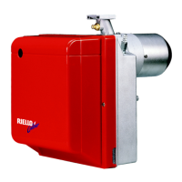
Do you have a question about the Riello BF5 and is the answer not in the manual?

Riello BF5 Specifications

General IconGeneral
BrandRiello
ModelBF5
CategoryBurner
LanguageEnglish

Summary

Single Stage Operation Oil Burners

Installation Precautions

Technical Data

Mounting the Burner to the Boiler or Furnace

Method 1 - Universal Mounting Flange

Details using the universal mounting flange to attach the burner to the heating unit.

Electrical Connections

Direct Line Voltage Wiring

Wiring diagram for 120V AC direct line voltage control circuit.

Low Voltage Wiring

Wiring diagram for 24V AC low voltage control circuit.

Application Field Wiring

Application Field Wiring - Riello 530 SE/C 24V Primary Control

Direct Line Voltage Wiring

Wiring diagram for 120V AC direct line voltage control circuit for 24V primary control.

Low Voltage Wiring

Wiring diagram for 24V AC low voltage control circuit for 24V primary control.

Installation and Removal of Drawer Assembly

Oil Line Connections

Single Line (Gravity Feed System)

Instructions for single line gravity feed setup, including fitting installation.

Two Line (Lift System)

Pump Purge

Setting the Air Adjustment Plate

Burner Start-Up Cycle

Burner Adjustment Tables

Model BF3 Burner Setup Chart

Initial setting chart for BF3, including nozzle, pressure, turbulator, and air damper.

Model BF5 Burner Setup Chart

Initial setting chart for BF5, including nozzle, pressure, turbulator, and air damper.

Trouble Shooting Chart

Related product manuals