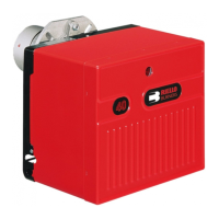
This document is an installation and operating manual for the Riello 40 single-stage oil burner, specifically the F15 model with a manual air shutter (Type 264T). It provides comprehensive guidance for installers to ensure proper setup, operation, and maintenance of the burner.
Function Description
The Riello 40 F15 burner is designed for single-stage operation, meaning it operates at a fixed firing rate once ignited. Its primary function is to provide heat by burning No. 2 fuel oil in a boiler or furnace. The burner is equipped with a primary control (Riello 530 SE/C 24V) that manages the ignition sequence, flame supervision, and safety lockout functions. An ignition transformer provides the necessary spark for combustion, while a motor drives the fan for combustion air and the oil pump for fuel delivery. The burner's design includes a turbulator and an air adjustment plate to optimize the air-fuel mixture for efficient combustion.
The burner can be configured for either a single-line (gravity feed) or a two-line (lift) oil supply system, with specific instructions provided for each setup, including the installation of a by-pass plug for two-line systems. Electrical connections are detailed for both direct line voltage and low voltage thermal input control circuits, emphasizing safety precautions and adherence to local electrical codes.
Usage Features
The manual outlines several key usage features and considerations for the Riello 40 F15 burner:
- Non-Retrofit Applications: For burners installed in packaged units (e.g., with a boiler or furnace), installers are advised to follow the heating unit's specific instructions, as settings may differ from this manual.
- Air for Combustion: Adequate air supply is crucial for proper combustion. The manual stresses the importance of ensuring sufficient air in the boiler/furnace room and suggests creating a window if necessary, in compliance with local ordinances (CSA standard B139 in Canada, NFPA manual #31 in the USA).
- Chimney Requirements: The chimney must be sufficient to handle exhaust gases, clean, clear of obstructions, and ideally connected only to the burner.
- Oil Filter: An external oil filter is mandatory, despite an internal pump strainer, and requires annual replacement.
- Draft Control: Maintaining combustion area pressure as close to zero as possible is recommended, with the burner designed to operate with a slight draft or pressure.
- Electrical Safety: All electrical connections must conform to national and local codes (C.E.C. Part 1 in Canada, National Electrical Code in the USA) and the system must be grounded. A service switch should be installed near the burner on a fireproof wall.
- Mounting Options: The burner offers three mounting methods: universal flange bolted to the boiler/furnace, semi-flange collar bolted to the boiler/furnace, or universal flange mounted to an optional pedestal.
- Nozzle Placement: Proper nozzle selection and placement, along with pump pressure, are critical for achieving the desired firing rate, guided by the Burner Set-up Chart.
- Turbulator Setting: The turbulator adjustment screw allows fine-tuning of the combustion air, aligning with specific index numbers from the Burner Set-up Chart.
- Air Adjustment Plate: The manual air adjustment plate controls combustion air flow, with initial settings provided in the Burner Set-up Chart. Final adjustments require combustion instruments to achieve optimal CO2 levels and zero smoke.
- Ducted Combustion Air Intake: An optional kit allows for direct external air intake, with specific setup charts provided for 4" and 6" diameter pipes, and guidelines for minimizing pipe length and insulating the intake.
- Burner Start-Up Cycle: The manual includes diagrams illustrating the normal start-up sequence and the lockout sequence due to light-failure, showing the timing of thermostat, motor, ignition transformer, valve, flame, and lockout lamp activation.
Maintenance Features
While primarily an installation guide, the manual touches upon several maintenance-related aspects:
- Oil Filter Replacement: The external oil filter is a required component that needs to be replaced at least once a year, with the filter container cleaned during this process.
- Pump Purge: Detailed instructions are provided for purging the oil pump in both single-line (gravity feed) and two-line (lift) systems to remove air, which is a critical step during initial setup or after running out of fuel. This process involves loosening bleeder valves, disconnecting supply lines, and using a light source on the photo-cell to ensure proper operation.
- Nozzle and Electrode Maintenance: Although not explicitly detailed as routine maintenance, the instructions for nozzle placement and electrode setting imply that these components may need to be accessed for inspection, cleaning, or replacement. The precise dimensions for electrode setting are highlighted as critical for proper burner function.
- Troubleshooting (Implied): The "Burner Start-Up Cycle" section, particularly the "Lock-out, due to light-failure" diagram, provides insight into potential operational issues and how the burner's safety system responds, which can aid in diagnosing problems.
- Spare Parts List: A comprehensive exploded spare parts list with corresponding codes and descriptions is included, facilitating the identification and ordering of replacement parts for maintenance and repairs.
- Burner Start-Up Report: This report serves as a record of initial settings and readings (e.g., oil supply/suction pressure, CO2, O2, flame signal, nozzle size, smoke number), which can be invaluable for future maintenance and troubleshooting to ensure the burner continues to operate efficiently and safely over time.