Brown
White (50V)
Blue
Motor
Capacitor
Regulating thermostat
Neutral
Switch with fuse
6A
max.
M
~
Grey
230V ~ 50Hz
LN
Limit thermostat
with manual resetting
Remote lock-out lamp
(230V - 0.5A max.), if required
1NT1T2S3B4
12
Brown
Valve
T
T
D5334
Black
TERMINAL
CONTROL-BOX
7 pin plug
7 pole socket
3456789
NL
Yellow/Green
Blue
Blue
Brown
Black
Hour counter
h
Black
Do not exchange the neutral with the phase
NOTES:
– Wires of 1 mm
2
section.
– The electrical wiring carried out by the
installer must be in compliance with the
rules in force in the Country.
TESTING
Check the shut-down of the burner by opening
the thermostats.
S7183
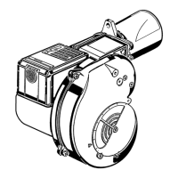
CONTROL BOX
- To remove the control-box from the burner,
loosen screw (A) (see figure) and pull towards
the arrow.
- The photoresistance is fitted directly into the con-
trol-box (underneath the ignition-transformer) on a
plug-in support.
RUN OF THE ELECTRICAL CABLE
1 - Grommet N - Neutral
2 - Cable-clamp L - Phase
3 - Terminal block - Burner-earth
- Lock-out lamp
ATTENTION
Do not connect burner’s grounding, to fail-
ure indicator terminal . This may result
the destroy of the control box.
CARRIED-OUT BY THE INSTALLER
CARRIED-OUT IN THE FACTORY
BLOCK OF
530SE
*