2361
7
GB
Combustion head settings indicated in the schedule are valid for most cases.
The setting of the fan output according to the installation should normally be done only through the air
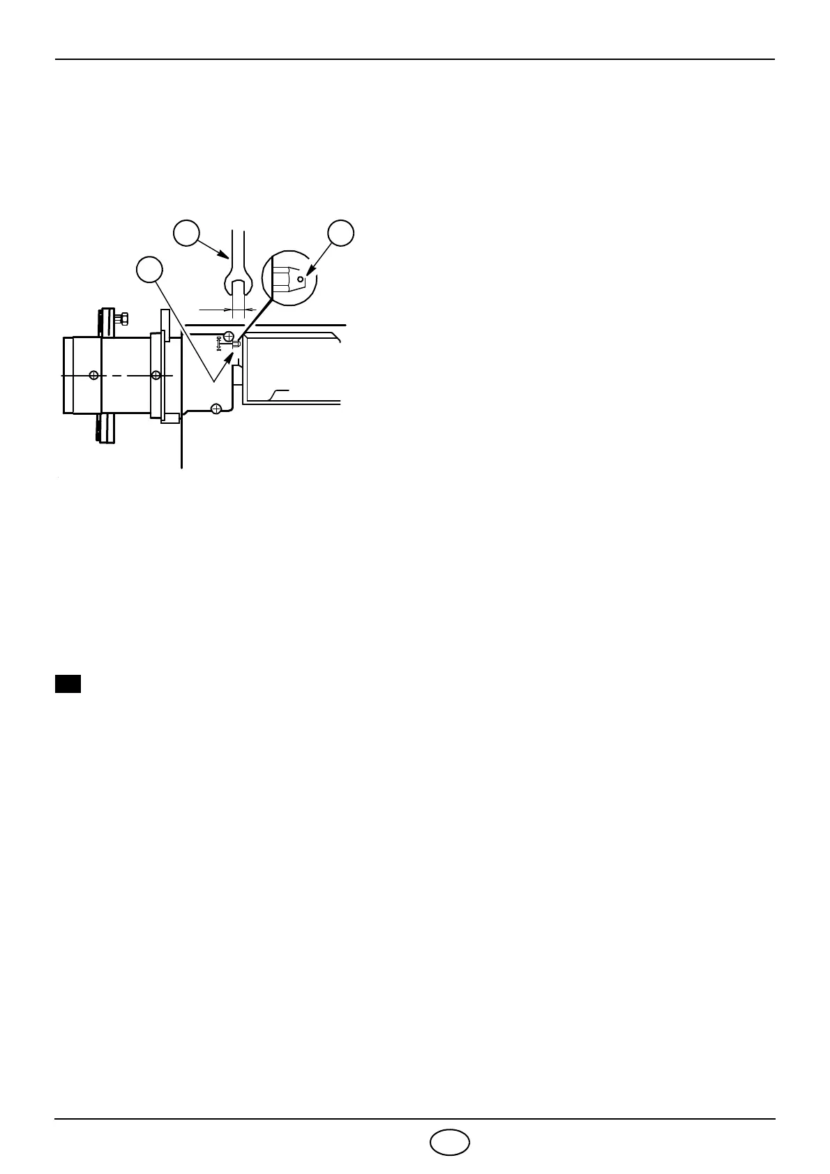
damper. Should one subsequently want to retouch also the setting of the combustion head, with the
burner running, operate on the rod (1) with a 6 mm spanner (2) as follows:
TURN TO THE RIGHT: (sign +)
In order to increase the volume of air entering the
combustion chamber and thus diminishing its pres-
sure.
There is a reduction of CO
2
and the adhesion of the
flame to the air diffuser disc improves.
(Setting advisable for ignitions at low temperatures).
TURN TO THE LEFT: (sign
–)
In order to reduce the volume of air entering the com-
bustion chamber and thus increasing its pressure. The
CO
2
improves and the adhesion of the flame to the
diffuser tends to reduce. (This setting is not advisable
for ignitions at low temperatures).
In any case do not bring the combustion head setting
more than one point away from that indicated in the
schedule. One set-point corresponds to 3 turns of the
rod; a hole (3) at its end facilitates counting the num-
ber of turns.
AIR DAMPER ADJUSTMENT: The settings indicated in the schedule refer to the
burner with its metal cover fitted and the combus-
tion chamber with “zero” depression.
These regulations are purely indicative.
Each installation however, has its own unpredicta-
ble working conditions: actual nozzle output; posi-
tive or negative pressure in the combustion-
chamber, the need of excess air, etc. All these con-
ditions may require a different air-damper setting.
It is important to take account of the fact that the air output of the fan differs according to
whether the burner has its metal cover fitted or not.
Therefore we recommended to proceed as follows:
– adjust the air damper as indicated in the schedule (4);
– mount the cover, simply by means of the upper screw;
– check smoke number;
– should it become necessary to modify the air output, remove the cover by loosening the screw,
adjust the air damper, remount the cover and finally recheck the smoke number.