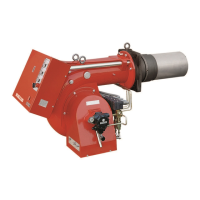
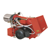
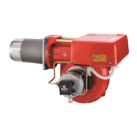
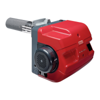
The provided document is an installation, use, and maintenance manual for Riello light oil burners, specifically models P200 T/G (Type 477 T80).
Function Description
The Riello P200 T/G is a light oil burner designed for heating applications, operating in three stages to provide flexible thermal output. It is suitable for boilers and similar heating systems, ensuring efficient combustion of light oil. The burner's operation involves a sequence of pre-purging, ignition, and flame stabilization across its three stages, controlled by an internal wiring system and a control box. It features a self-diagnostic system to identify operating faults and provides indications for various operational states and errors.
Important Technical Specifications
Thermal Power - Output:
- Range: 530 / 2370 kW (45 / 200 kg/h)
- Operation: 1st stage - 2nd stage - 3rd stage
- Fuel: Light oil, maximum viscosity at 20°C: 6 mm²/s (1.5° E)
Electrical Data (Motor IE1):
- Electrical Supply: Three-phase 220V +10% -10% ~ 60Hz without neutral; 380V +10% -10% ~ 60Hz with neutral
- Motor: 15.9 A / 220V - 9.2 A / 380V
- Ignition Transformer: Primary: 2 A; Secondary: 2x 6.5 kV - 35 mA
- Absorbed Electrical Power: 5.5 kW
Electrical Data (Motor IE2):
- Electrical Supply: Three-phase 220V +10% -10% ~ 60Hz without neutral; 380V +10% -10% ~ 60Hz with neutral
- Motor: 14.6 A / 220V - 8.5 A / 380V
- Ignition Transformer: Primary: 2 A; Secondary: 2x 6.5 kV - 35 mA
- Absorbed Electrical Power: 5.5 kW
Dimensions (mm):
- Overall length: 890 mm
- Burner width: 796 mm
- Boiler front plate drilling: 255 mm diameter, M16
- Combustion head projection: 281 mm (can be extended with a spacer)
Pump Pressure and Nozzle Delivery:
- Pump leaves the factory rated at 12 bar.
- Maximum pump pressure values should not exceed 10 and 14 bar.
- Nozzles are 60° type.
- Nozzle delivery varies based on pump pressure (e.g., at 12 bar, 8.00 GPH nozzles deliver 34.3 kg/h).
Combustion Head Adjustment:
- Adjustable based on maximum output, with specific set-points (e.g., Set-point 6).
Air Damper Adjustment:
- Independent adjustment for 1st, 2nd, and 3rd stages, controlled by hydraulic jacks.
Usage Features
Operation and Efficiency:
The burner operates in three stages, with specific power and output ranges for each stage:
- 1st Stage: Ignition phase (1st nozzle), intermediate phase (1st + 2nd nozzle), operation phase (1st + 2nd + 3rd nozzle).
- Minimum: 391 kW (33 kg/h) to 1186 kW (100 kg/h)
- Maximum: 782 kW (66 kg/h) to 2372 kW (200 kg/h)
- 2nd Stage: Ignition phase (1st nozzle), 1st stage of operation (1st + 2nd nozzle), 2nd stage of operation (1st + 2nd + 3rd nozzle).
- Minimum: 391 kW (33 kg/h) to 1186 kW (100 kg/h)
- Maximum: 782 kW (66 kg/h) to 2372 kW (200 kg/h)
- 3rd Stage: 1st stage of operation (1st nozzle), 2nd stage of operation (1st + 2nd nozzle), 3rd stage of operation (1st + 2nd + 3rd nozzle).
- Minimum: 557 kW (47 kg/h) to 1186 kW (100 kg/h)
- Maximum: 794 kW (67 kg/h) to 2372 kW (200 kg/h)
Supply Line:
- Requires proper installation of suction and return lines.
- Max depression of 0.45 bar (35 cm Hg) should not be exceeded to prevent fuel turning into gas.
- Foot valve is indispensable if the return line is above the fuel level.
Pump Priming:
- Involves loosening the tap from the vacuometer plug, filling the pump with light oil, operating the burner, purging air from the manometer plug, and waiting for priming.
Electrical Connections:
- Detailed internal wiring diagram provided.
- Connections to the wiring terminal block are to be carried out by the installer.
- A radio disturbance protection kit (Code 3010386) is available for installations in areas with high electromagnetic interference or long thermostat connections (>20 meters).
Electric Panel:
- Features hourcounters for 1st, 2nd, and 3rd nozzles, motor lock-out signal, a 4-position commutator, and a control box lock-out signal with reset push-button.
- The commutator allows selecting burner operation modes:
- Pos. 0: Burner stop
- Pos. 1: Burner operation only at 1st stage
- Pos. 2: Burner operation at 1st and 2nd stage
- Pos. 3: Burner operation at 1st, 2nd and 3rd stage
Start-Up Cycle:
- Normal start-up sequence includes thermostat activation, motor, ignition transformer, safety valve, and flame valves (1st, 2nd, 3rd).
- Alternative start-up cycles can be configured by modifying wiring at the control box terminals to adjust pre-ignition presence or pre-purge period.
Diagnostics:
- The control box has a self-diagnostic system with a RED LED signal to indicate operating faults.
- Fault codes are communicated via a sequence of LED flashes after a lock-out and reset.
- Common probable causes for faults include faulty photocell, oil valves, ignition transformer, burner regulation, air pressure switch issues, loss of flame, oil enabling thermostat fault, or wiring errors.
Maintenance Features
Combustion Head Adjustment:
- Adjustment is made by turning screws until the set-point aligns with a washer (B).
- The real nozzle delivery can vary by ±5% and can be checked by weighing the oil sprayed from the nozzle.
Air Damper Adjustment:
- To open or close air dampers, loosen the ring nut (1) and turn the hexagonal body (2) clockwise to decrease air flow or counter-clockwise to increase it.
- Combustion results in all three stages should be checked to ensure proper adjustment.
Motor Lock-Out:
- Caused by overload relay or lack of electric supply.
- Reset by pushing the appropriate button after removing the protective cover.
Safety Precautions:
- Before operation, ensure the return line is open to prevent damage to the pump seal.
- High voltage warning for electrical checks.
- In case of repeated burner lockouts, contact After-sales Service. Interventions should only be made by qualified, authorized personnel.