20049136
8
Installation
4.6.1 Electrical wiring on burners with 6 pin plug-
socket
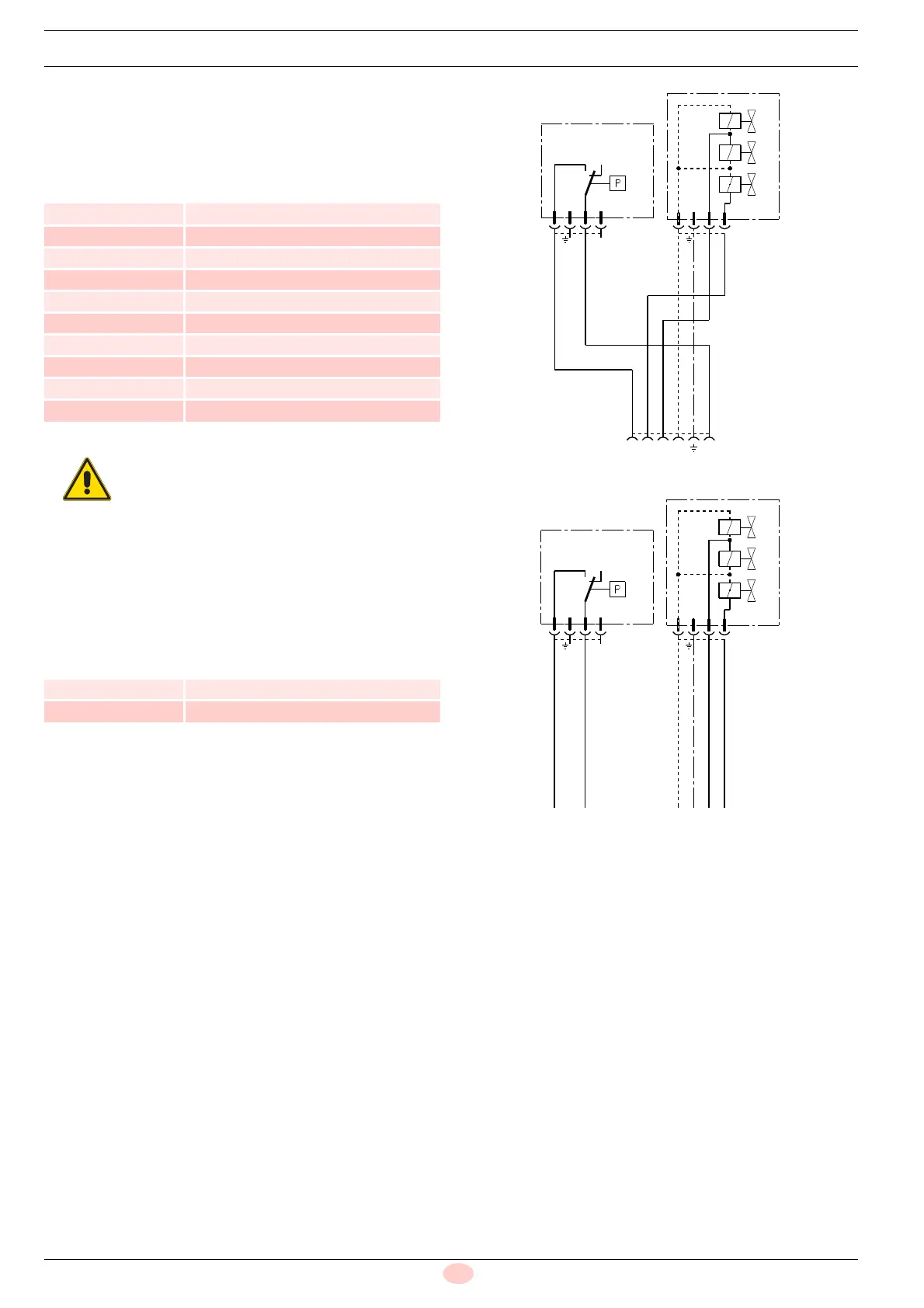
The gas trains shown in Tab. D are prepared in the factory to be
connected in accordance with the electrical diagram shown in
Fig. 4.
Tab. D
4.6.2 Connections for burners with terminal board
The gas trains shown in Tab. E are prepared in the factory to be
connected in accordance with the electrical diagram shown in
Fig. 5.
Tab. E
Key
PG Min gas pressure switch
V Valve group V1 - V2 - VS
X6 6 pole socket
BN Brown
BU Blue
BK Black
YE Yellow
Code Model
3970084 MB 405/2 - RSD 20
3970539 MB 405/2 - F1SD 20
3970540 MB 405/2 - F2SD 20
3970537 MB 407/2 - RSD 20
3970538 MB 407/2 - F2SD 20
3970541 MB 407/2 - F3SD 20
3970534 MB 410/2 - RSD 20
3970542 MB 410/2 - F3SD 20
3970543 MB 412/2 - F3SD 20
3970582 MB 415/2 - F3SD 20
For RS, RLS, RS/M model burners, it is neces-
sary to remove the 6 pole plug from the train
connection and replace it with the 6 pole plug
supplied with the burner, in accordance with
the electrical diagram shown in the burner in-
struction manual.
Code Model
3970556 MB 407/2 - RT 20
3970557 MB 410/2 - RT 20
321 N Ph
N
V1
BU
YE
BK
BN
V2
V1
V2
3
21
1
23
V
P
P
VS
PG
BU
YE
BK
BN
PG
V1
V2
3
21
1
23
V
VS
P
P
V2
V1
N




 To Next Page