10
CONTACTS PORT
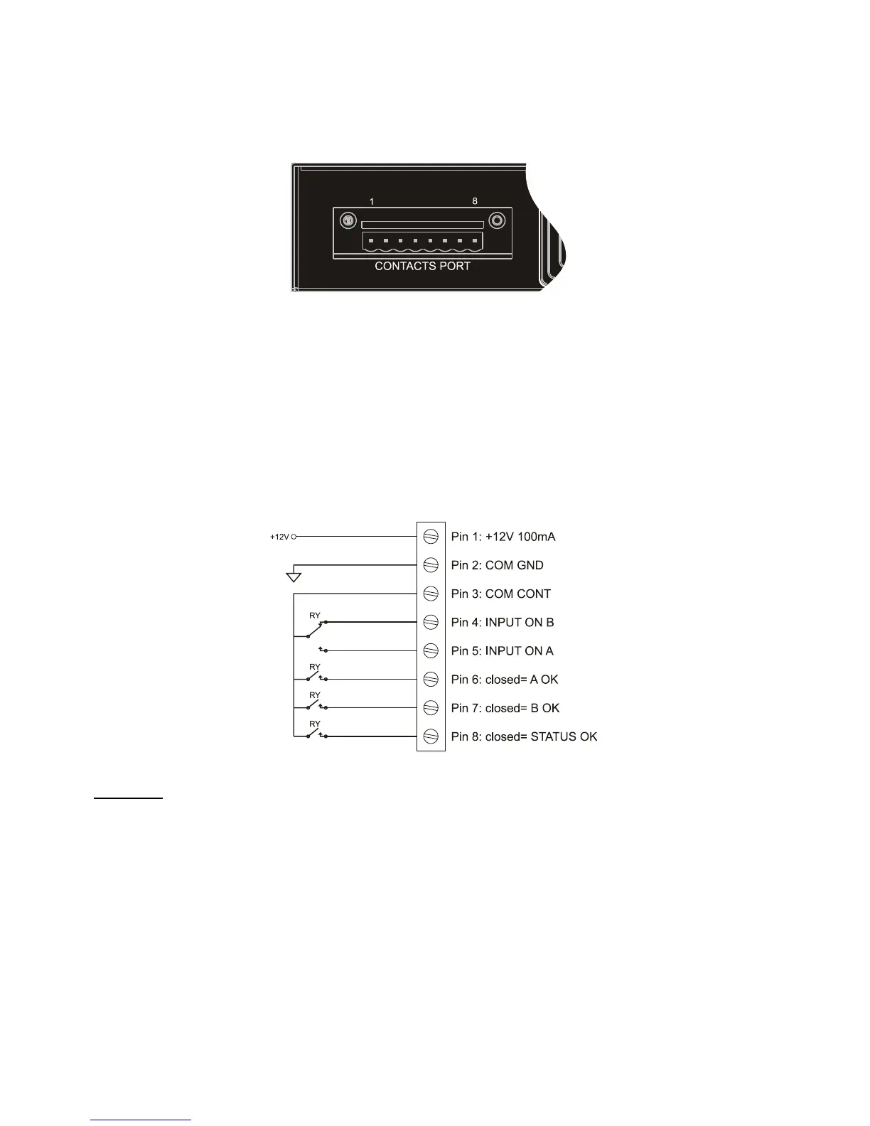
The contacts port is formed using eight (8) pins numbered from left to right (see fig. 9), which can be connected to an external
monitoring system (such as a BMS) in order to monitor the operational status of the ATS.
The external equipment must respects the voltage and current characteristics of contacts port.
Fig. 9: Focus on contacts port.
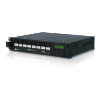
The contacts port provides the following pins:
Pin 1: supplies +12V d.c. and a maximum 100mA current usable as user needs.
Pin 2: GND.
Pin 3: common contact.
Pin 4: “INPUT B” active contact (if the contact between “pin 4” and “pin 3” is closed, output is supplied by “INPUT B”).
Pin 5: “INPUT A” active contact (if the contact between “pin 5” and “pin 3” is closed, output is supplied by “INPUT A”).
Pin 6: “INPUT A” OK contact (if the contact between “pin 6” and “pin 3” is closed, “INPUT A” is present and regular).
Pin 7: “INPUT B” OK contact (if the contact between “pin 7” and “pin 3” is closed, “INPUT B” is present and regular).
Pin 8: Status OK contact (if the contact between “pin 8” and “pin 3” is closed, ATS functioning status is regular).
The following diagram shows the fuctioning of the contacts port.
Fig. 10: Contacts port basic diagram.
ATTENTION: the pins of the contact port are able to carry a 1A maximum current and 48V maximum voltage.